Setting Up a Stanley Gage Plane

Stanley Gage Plane - Frog and Iron Assembly

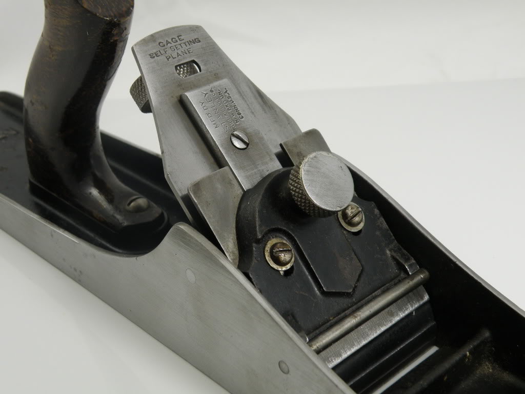
Stanley Gage Plane – Frog and Iron Assembly

Stanley Gage planes are a little finicky to set up initially, but once you get them set accurately, they do tend to stay that way.  The main benefit of the design is such that once properly set, you can remove the lever cap, iron and cap iron, and then replace them again, returning to the exact depth adjustment at which you had it set initially.  Further, since the iron/cap iron is positioned via an indexing block, there is no slop (movement) from side to side, and therefore no need for a lateral adjustment mechanism.

Indexing Block on Gage Iron

Indexing Block on Gage Iron

Some people will tell you that in order for the design to work, the cutting edge of the iron must be perfectly perpendicular to its edges.  Ideally, that is true.  However, I don’t think it’s actually all that critical.  What does need to be perpendicular to the cutting edge is the sides of the indexing block, which can be loosened and adjusted via the screw on the top side of the iron (show here on the left).

The indexing guide itself, which is attached to the lever cap, is not laterally adjustable, so in order for the iron to extend properly through the mouth of the plane, the iron’s edge needs to be perfectly aligned.  As I said, you ideally want everything to be at perfect right angles, but that’s not always what you end up with. By adjusting the indexing block so that it’s properly aligned in conjunction with the cutting edge on the iron, even a skewed edge can be aligned properly.

I admittedly don’t have a lot of extensive personal hands-on experience with the Gage planes.  I’ve owned a couple, and right or wrong, here’s how I set them up for use:

  1. Remove the lever cap and set it aside.
  2. Loosen (slightly) the indexing block that’s attached to the iron, just enough so it moves independently against the iron.
  3. Put the iron in place (seating the indexing block to engage the depth adjustment).
  4. Align the iron with the mouth opening, and carefully tighten the screw on top of the indexing block.
  5. Put the lever cap in place and tighten it.  You should be good to go.

***

Stanley Gage Planes – History and Type Study

John Porcius Gage formed the Gage Tool Co. in 1883, and operated it until 1917, making wood bottom transitional planes. J.P. Gage registered plane patents on 4 August 1885, 13 April 1886 and 8 November 1892. The 30 January 1883 patent of David A. Ridges was also used.

US339872-Gage-Patent

J. P. Gage Patent Drawing

The Gage “self-setting” design eliminated the need for a lateral adjustment feature, which eliminated slop in the blade movement. The adjustment slide was designed to accurately fit into a groove in the frog, and depth adjustment was controlled by a screw at the rear of the frog, similar to a low angle block plane. The two-piece lever cap design also functioned as a chipbreaker. The outer part of the cap serves as the lever cap, with the inner piece functioning as a chipbreaker. The mechanism is adjustable via a two-screw slide to bring it closer to the edge of the blade. The self setting feature allowed the cutter and cap to be removed and reinstalled without adjustment of the cut.

In 1919 Stanley Rule & Level Co. bought the Vineland NJ company, mainly to get the patent for their excellent frog design and to compete with Sargent’s Auto-Set line of planes that are very similar in both appearance and design. Stanley retained the use of the Gage name, producing a line of transitional planes from 1919 to 1935, and metal Gage planes from 1919 to about 1941, when the line was phased out.

The original Stanley Gage line of metal bench planes was numbered 3 through 7, sizes that compared to their Bailey counterparts. The G prefix was added in 1930 to distinguish them from the Bailey line (G3 through G7C). There were 10 different numbers included in the offering, which included corrugated versions that, like Bailey planes, were differentiated with a C suffix appended to the model number (ex. G3C or G7C).

Gage Plane

Stanley Gage no. 5, Type 2 (1924-1930)

Gage Type Study

There are four “Types” of Stanley Gage planes, which are thankfully far less complicated than most of the other Stanley Type studies.

Type 1 (1919-1923) – Plane beds marked “Pat. Appl’d For” in the casting. No “G” prefix to the model number

Type 2 (1924-1930) – “Pat. Appl’d For” removed from the casting. Plane beds are now marked with Schade’s 2-17-20 patent date.

Type 3 (1930-1941) – The “G” prefix added to the model number.

Type 4 – Same as Type 3 but has “Made in USA” added to the casting. (exact date of this is uncertain)


Sellens, Alvin, The Stanley Plane,: A History & Descriptive Inventory, Augusta, KS: Allvin Sellens, 1978.

Walter, John, Stanley Tools: Guide to Identity & Value, Marietta, OH: John Walter, 1996.

***