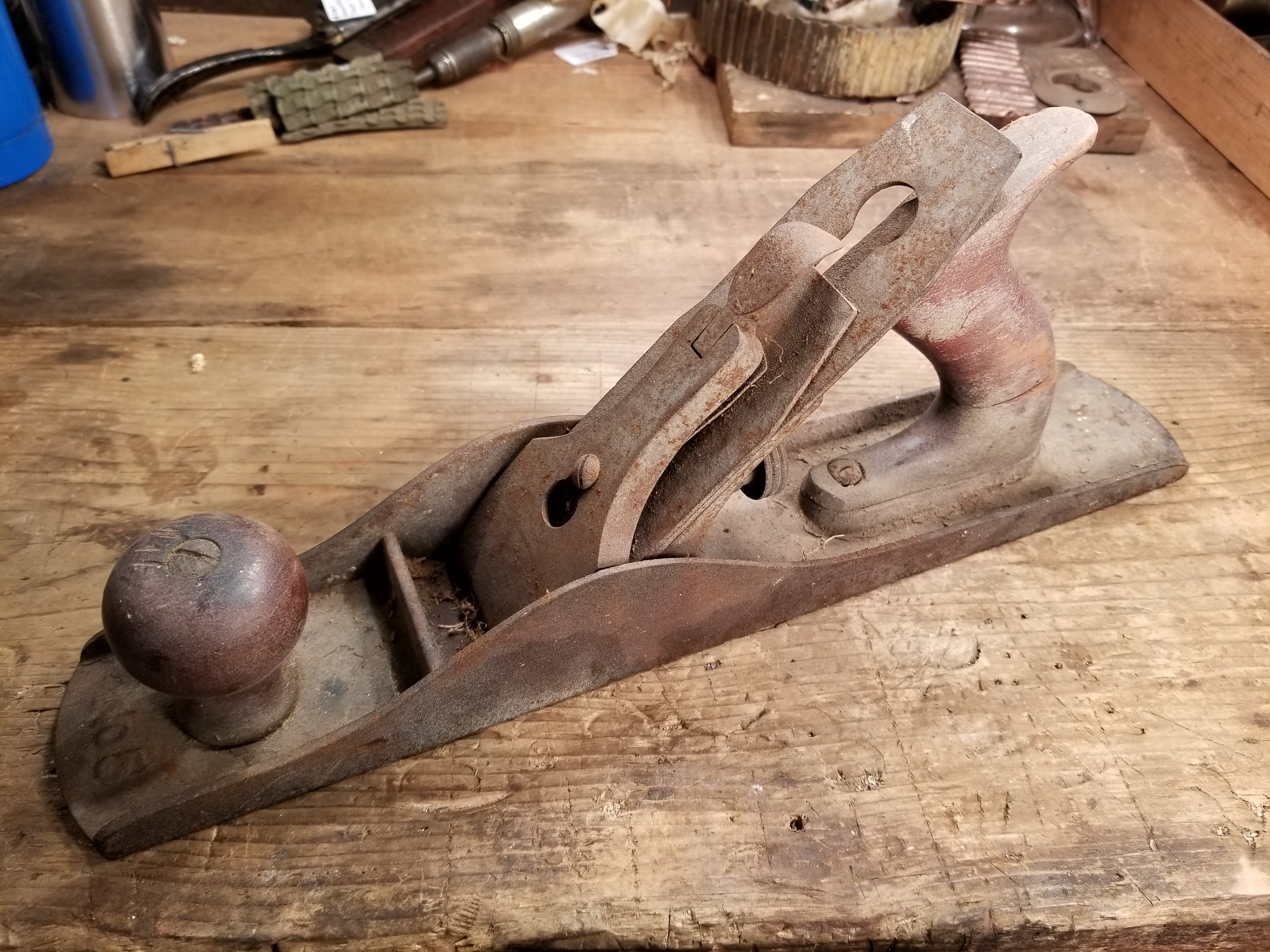
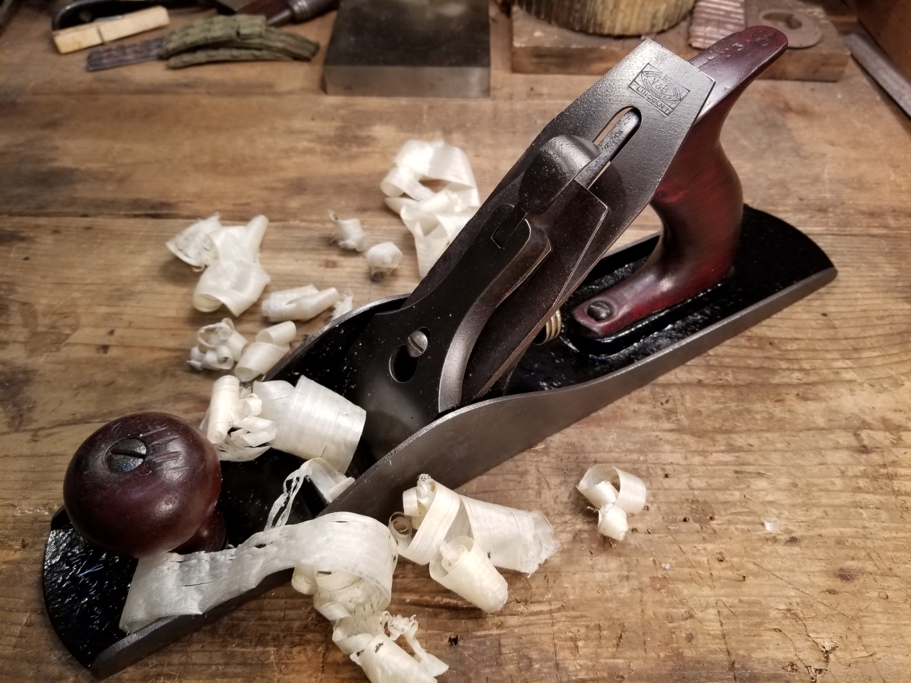
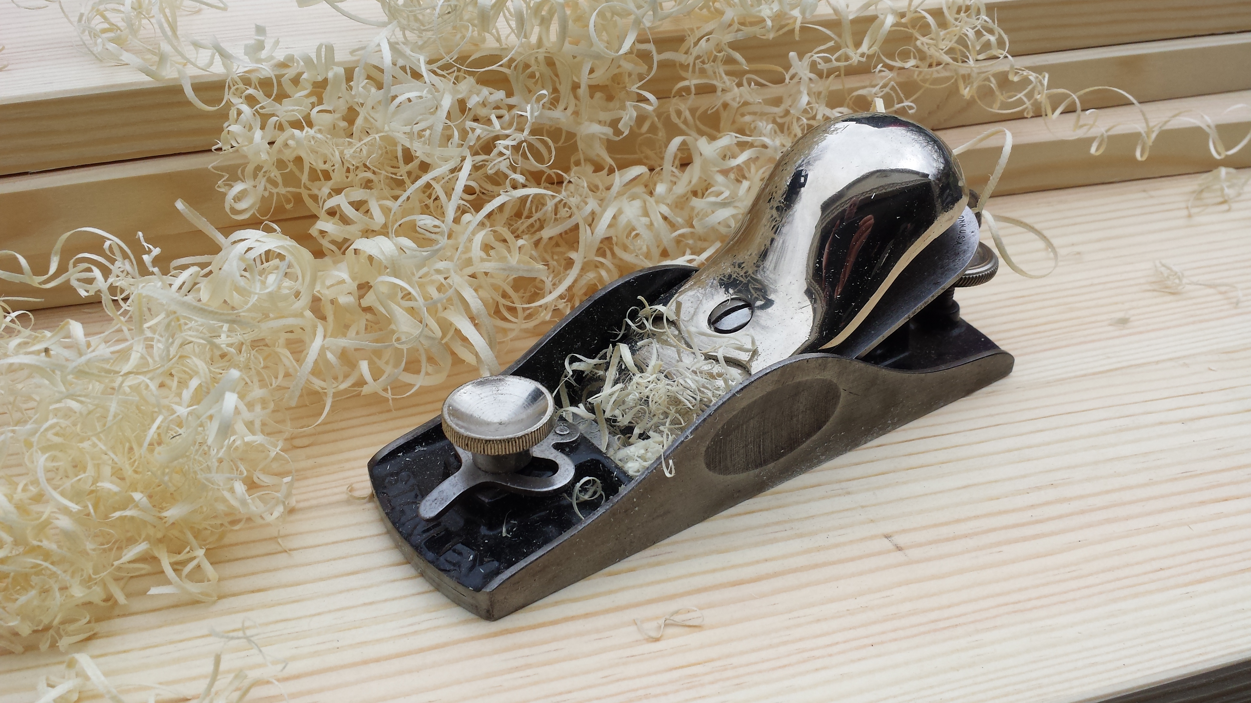
Stanley Bailey no. 9-1/2, c. 1952-55 ~ one of the most popular block planes of all time
As a follow up to an earlier post about setting up and tuning bench planes, this one will focus solely on block planes. Some of the information is taken directly from that post, so if you’ve read it, it may sound familiar.
On to Setting Up Those Block Planes…
It’s no surprise that so many ‘modern’ woodworkers, especially those used to plug-and-play electric tools, eschew anything that requires sharpening, let alone tuning and fettling to make it work properly. But the fact is, whether 100 years old or brand spanking new, virtually all planes benefit from some degree of tuning to bring them to their full potential. Fortunately, this is not a difficult proposition, and actually aids in better understanding how the tool functions and how to get the most out of it.
Below are the basic steps for setting up and tuning a block plane for use. Block planes tend to be less complicated than bench planes, but there are still many variations, both new and used. I’m purposefully keeping it fairly generic, so some interpretation may be necessary when applying the concepts to the tool in front of you. But don’t worry, there are no tool police surveilling workshops and garages. Feel free to skip a step if you don’t think it’s relevant or needed.
Step 1 – Soles Need Saving
I’m not a stickler when it comes to flattening the sole of a plane. After owning hundreds and using dozens of planes over the years, it’s fairly rare to come across one with a sole so warped, cupped, or bowed that it’s unusable. If you happen upon one that is truly unusable, my advice is to return it, sell it, or throw it away. The only possible exceptions are block planes, which are pretty easy to flatten due to their smaller size. Bench planes are far more difficult, especially the larger ones. You can take them to a machine shop and have them milled or lapped flat, but forget trying to flatten them yourself with sandpaper unless the problem is very minor.

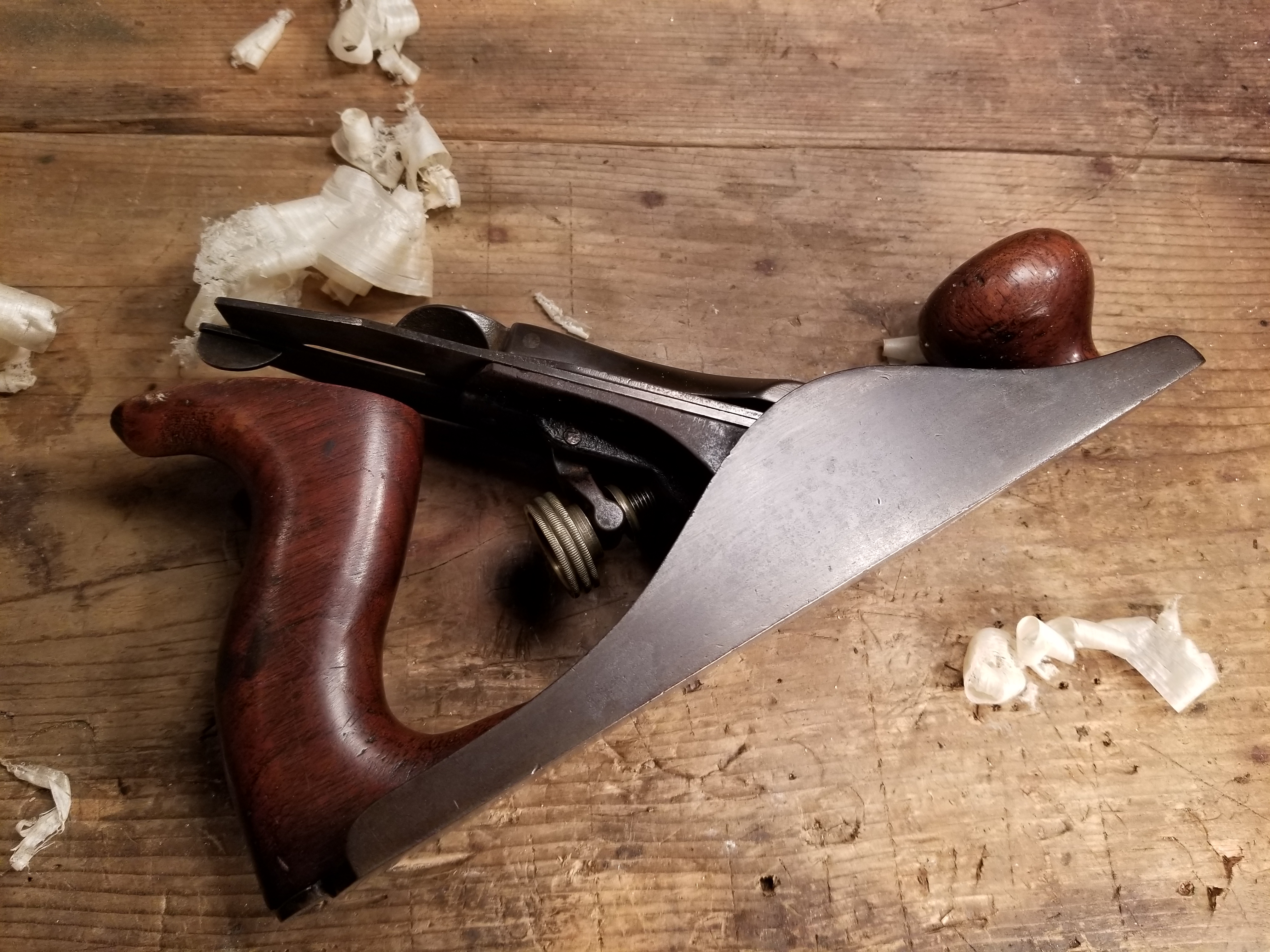
The sole of this plane was lapped by hand using a granite surface plate
If you do decide to lap your plane’s sole flat, you’ll need a dead flat substrate. The cast iron bed of a table saw or jointer works well, or if you don’t have one of those available and want to keep it on the cheap, a piece of 12” x 12” or larger granite surface plate will work for block planes. Just make sure you retract the blade and tension the lever cap as you would in actual use. This puts the correct stress on the plane body. I start with 60 grit and progress up to about 320. Removing high spots (convexity) is more critical than low spots (concavity). Keep in mind that you don’t even need the entire sole dead flat. As long as you have smooth contact at the toe, around the mouth, and at the heel, the plane will work just fine.
Vintage planes often have raised dings from bouncing around in tool boxes, especially along the edges, toe or heel. A flat mill file makes very quick work of these minor problems. Finally, some woodworkers file a very small 45 degree chamfer along each edge of the sole. This is completely optional, but helps prevent inadvertent gouges when using the plane should you tip it slightly. I’ve seen some Stanley planes from the mid 20th century that appear to have been made that way at the factory.
Step 2 – Flatten ‘dem Frogs

The hole in the iron straddles the lateral adjustment pivot disc and seats against the tiny frog where it engages the tiny pins on the height adjustment lever mechanism
Block planes do not typically have removable frogs like bench planes, but there are some exceptions, mainly on some of the specialty and low angle planes where part of the frog moves with the iron when adjusting depth of cut. Either way, the function of the frog is the same on all planes. It provides a secure platform on which the iron is supported. In order for the plane to shave wood correctly, there must not be any movement (wobble, play, rocking, etc.) to the iron. It must be firmly seated against the frog, so the face of the frog must be as flat and secure as possible. This platform on most block planes is frequently very small, especially when compared to bench planes. Click on the photo to the right and you can see the frog is less than 1/2 square inch.
Since the frog on your block plane is typically not removable, you only need to touch up the seat with a firm sanding block to ensure it is flat. Also, because the flat sloped area behind the mouth on the plane’s base provides much of the forward support for the iron, it needs to be flat too. Unfortunately, it’s hard to get to, and since you don’t want to enlarge the mouth at all, just a touch using a small piece of angled wood with fine sandpaper wrapped around it is about as far as you want to take it. Thankfully, this is all that is usually needed to remove old crud. A Dremel or quality flexible shaft tool with a wire wheel brush will also work if the problem is limited to dirt and light corrosion. Finally, as on the bench plane, clean the threads on all the hardware and add a little light oil to help retard moisture and rust.
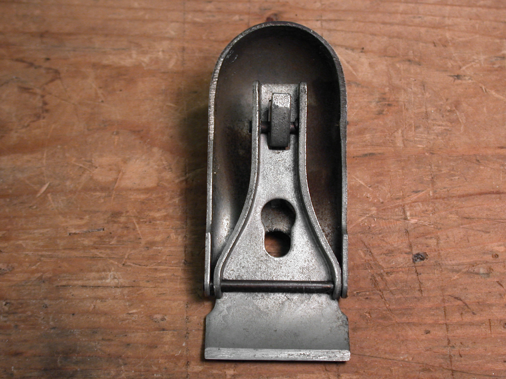
Step 3 – Lever Caps (This is not a drinking game…)

Just the leading edge to the underside of the lever cap at the bottom of the photo needs to be flattened. This photo, taken before flattening, shows the edge to be a little rough, which will compromise flush contact with the iron.
Block planes don’t have cap irons, so the lever cap plays a more important role. Use your coarse sharpening stone or take a fine file to the back side and remove any rough spots, giving close attention to the leading contact edge. This is most important on block planes with cast iron hooded style lever caps, such as the old Stanley 9-1/2. The back sides of these caps are notoriously rough and unfortunately japanned. You don’t need to remove all the japanning, but you do want to get a smooth line of contact down front where it touches the iron along the front edge. File it smooth and give it a couple of swipes across your 1000 grit stone. If your plane uses one of the nickel plated knuckle style lever caps, just flatten the bottom of the front edge in a similar fashion.
Step 4 – I Pity the Fool Who Don’t Sharpen His Tool!

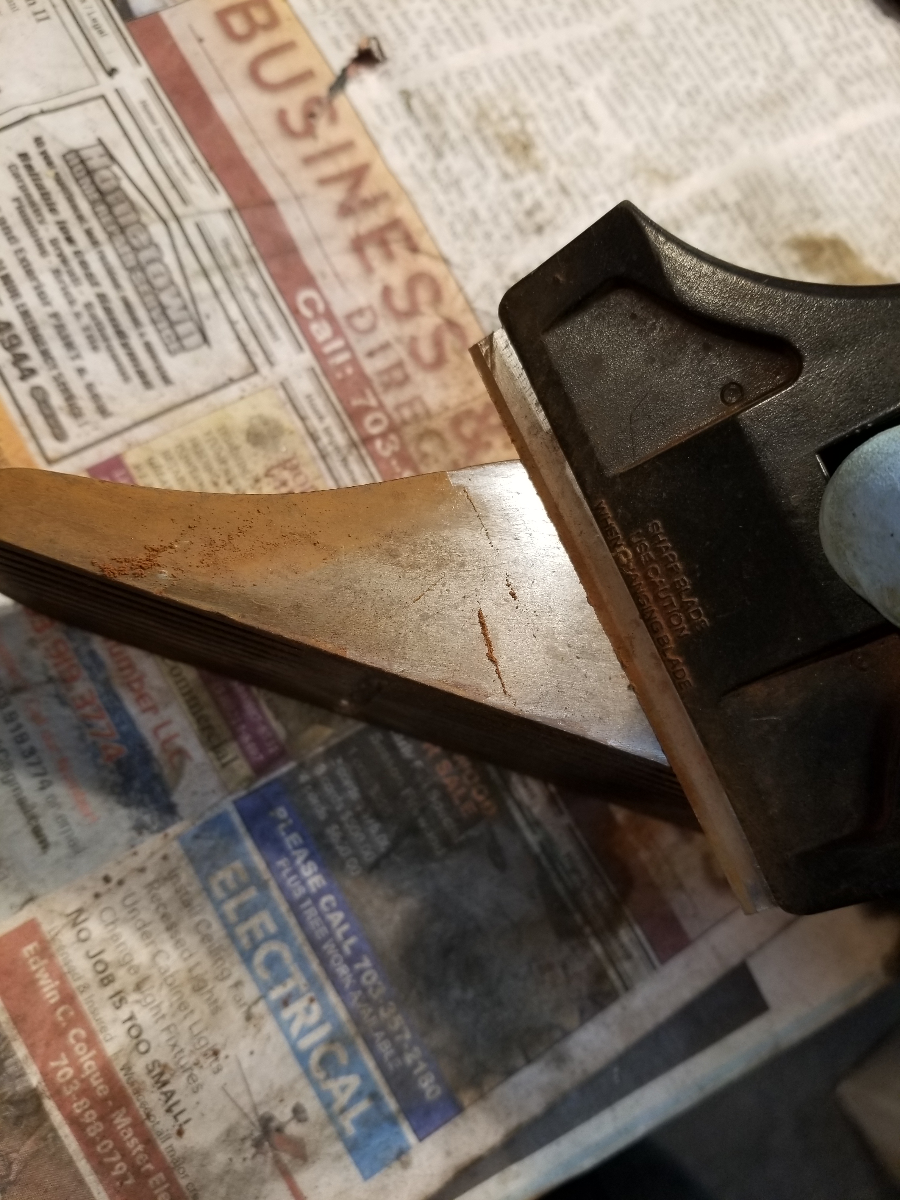
The iron has been sharpened with a small 2 to 3 degree secondary bevel added (the dark line at the very edge)
The simple fact is, even with brand new planes, the irons require final honing before use. This is not due to some lack of attention on the part of manufacturers. Irons are provided this way on purpose, since the manufacturer has no way of knowing what you will be using the plane for, and subsequently how the iron would need to be honed. You may want a perfectly straight edge if working on joinery, or you may want it cambered (with a slight radius) for smoothing out small surface areas. It’s up to you, but if you do nothing else in the way of tuning or preparing your plane for use, at least take the time to properly sharpen it. Do not skip this step! Sharpen the iron. Again, sharpen the iron! Sharpen it I say!
Since sharpening is such an expansive topic in and of itself, I will leave the specific details for other posts. What you need to know in the context of tuning, however, is that any plane, new or old, requires initial sharpening and honing. At a minimum, new plane irons need to have their un-beveled side honed flat and polished to at least 4000 grit and preferably 8000 grit. You don’t need to fuss with the entire surface; just the first 1/8” to 1/4” along the cutting edge will do. You also need to put a final honing on the bevel edge itself. It may look sharp, but it needs to be honed, again, to at least 8000 grit. The goal is to get your cutting edge to as close as possible to a zero degree radius.
Sharpening is too often the deal breaker that dissuades woodworkers from trying hand tools. This in unfortunate, for it requires little monetary investment to get started, is not particularly difficult to learn, and can be accomplished rather quickly with surprisingly good results. For detailed information on sharpening, I recommend investing in one of the outstanding books on the subject by Ron Hock or Leonard Lee. Chris Schwarz has also written a number of fantastic articles on sharpening plane irons.
Step 5 – Final Adjustments
Now that you’ve finished tuning and sharpening your plane, it’s time to put it all back together and adjust it for use. Hopefully, you have a better understanding of what each part does and how they all function together. This will make adjusting it for use, and while in use, more intuitive and fluid.
A few points of consideration…

The adjustable mouth plate on the Stanley no. 9-1/2. The mouth opening is adjusted by loosening the knob and rotating the eccentric throat lever left or right (to open or close the mouth).
While the frog’s position on bench planes is adjustable, meaning you can shift if forward to decrease the size of the mouth opening or backward to increase the size of the opening, many (but not all) block planes have adjustable mouths. Use a larger mouth opening for thicker cuts, and a smaller mouth opening for fine shavings. For details on this please see my post on adjustable mouth planes.
Holding the plane upside down, and looking down the sole at a low angle, lower the iron until it just begins to appear through the mouth – just a whisper. Note that it’s not unusual for there to be quite a bit of slop in the wheel that lowers and raises the iron, as much as a full turn or two. Just turn it until you begin to feel resistance. Make any lateral adjustments necessary using the lateral adjustment lever if your plane has one (some do and some don’t). If yours doesn’t, just tap the side of the iron with a small hammer to properly align it. I use a brass hammer so as not to mushroom the iron’s edge, but what you use is up to you. Turn it upright and make a test pass on a piece of scrap wood. If the plane digs in, back off the depth just a bit. If it misses entirely, lower the iron a little. You will quickly get a feel for when it’s ‘right,’ as evidenced by the rewarding ‘thwack’ sound a plane makes when it cuts a perfect curl.
Tuning a hand plane is not a difficult endeavor. Once practiced, the whole process can be accomplished in about a half hour, even less depending on the tool. Rather than view it as an unpleasant chore, I actually enjoy it, especially later in the evening when the dust has settled and the world is quiet. Pour yourself a measure (or two) of your favorite Kentucky brown, put on some music of choice, and saddle up to your work bench.

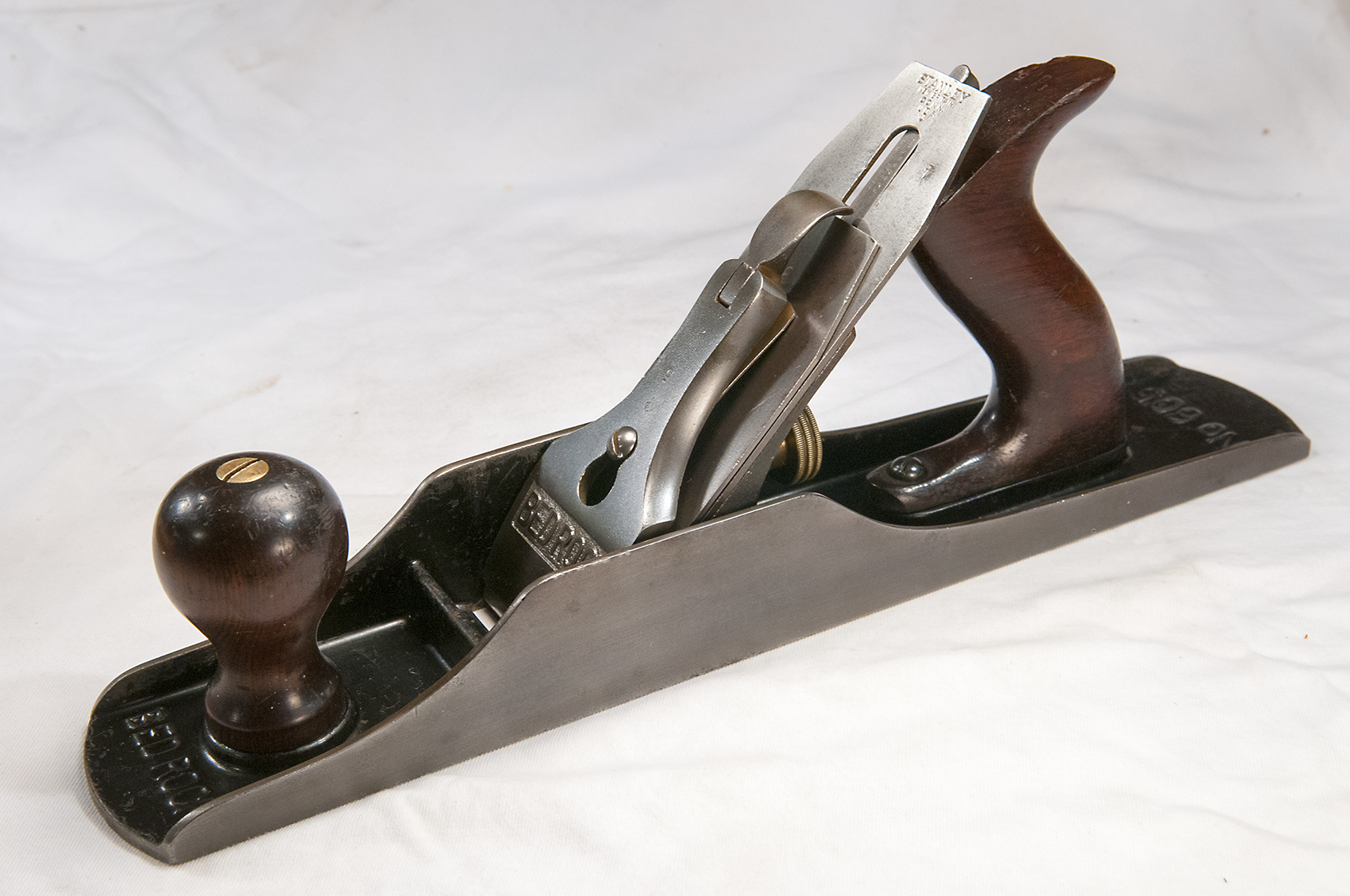
Stanley Bailey no. 18, c. 1936-42
***
Tools shown in the photos were returned to functional condition by Virginia Toolworks using museum quality archival preservation techniques. Sharpened and tuned for use, every tool is fully tested and adjusted until perfect.