Five Confusion-Busting Facts About Type Studies

dsc02972

Five important confusion-busting facts about Type Studies:

    1. Type Studies are modern-day timelines used to identify the age of a tool by referencing important changes in its design, manufacture, and physical characteristics.  Different ‘Types’ within a Type Study refers to a particular period of manufacture in which a particular feature or set of features was unique.
    2. Manufacturers didn’t adhere to Type Studies because Type Studies did not exist at the time.  They simply manufactured tools and made periodic changes to design and manufacturing processes, just like manufacturers today.  We identify those periodic changes in the Type Study, and subsequently assign ‘Types’ based on the time period in which they were made.
    3. Type Studies are not interchangeable.   They only apply to a specific model or series of tools.  Different tools and different lines will have different Type Studies.  For example, Stanley’s Bailey line of bench planes have a completely different Type Study from the Bed Rock series.   Some tools, like the no. 71 router plane, have their own individual Type Study.  Many tools have never been studied in depth and don’t have a Type Study at all.
    4. Type Studies are approximations.  The manufacturing timeline was constantly evolving.  Even when design changes were made, existing (old) stock parts were used until their supply was depleted before moving to new parts.  Therefore, the changeover of features sometimes took months or even years, resulting in multiple variations of the same product being released at the same time.  While Type Studies imply that these changes were aligned with a specific date or year, collectors need to understand that the transitions were more evolutionary than revolutionary.
    5. Type Studies are not all-inclusive.  With some manufacturers and some tools, and some tools made during certain periods, features and materials varied quite a bit.  A good example of this is Stanley’s offering of Bailey bench planes made during World War II.  Brass was in short supply, and subsequently, the so-called Type 17 planes made during the war years have a variety of inconsistencies.  Some had brass hardware, where others have steel.  Some have rosewood knobs and totes, while others have painted hardwood.  Some have frog adjustment mechanisms while others don’t.   All made during this period, however, are considered Type 17, regardless of features.

Video History of The Stanley Works


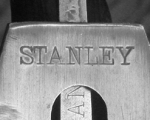
Stanley Trademark Stamps

The following reference guide provides examples of Stanley’s trademark stamps from 1872 to the present. It is by no means comprehensive or complete, but this covers the main trademarks. There were often variations used on block planes and other tools. Some of the photos are pretty poor. I will try to photograph better examples as time goes by.

A.1 Trademark (1872-1874)

A.1 Trademark (1872-1874)

A.4 Trademark (1879-1885)

A.4 Trademark (1879-1885)

A.5 Trademark (1886-1890)

A.5 Trademark (1886-1890)

J Trademark (1874-1884) *Longer on Block Planes

J Trademark (1874-1884*) *~1909 on Block Planes

JJ Trademark (1890-1910) Used on Block Planes

JJ Trademark (1890-1910)
Used on Block Planes

P Trademark (1886-1890)

P Trademark (1886-1890)

Q Trademark (181-1904)

Q Trademark (1891-1904)

S Trademark (1907-1909)

S Trademark (1907-1909)

T Trademark (1909-1912)

T Trademark (1909-1912)

V ("Victory") Trademark (1912-1918)

V Trademark (1912-1918) Also called “Victory”

X Trademark (1919-1920) 1st "Sweetheart"

X Trademark (1919-1920)
1st “Sweetheart”

X Trademark (1919-1920) Block Plane Variation

X Trademark (1919-1920)
Block Plane Variation

X Trademark (1919-1920) Block Plane Variation

X Trademark (1919-1920)
Block Plane Variation

X Trademark (1919-1920) Block Plane Variation

X Trademark (1919-1920)
Block Plane Variation

Y Trademark (1920-1921) 2nd "Sweetheart"

Y Trademark (1920-1921)
2nd “Sweetheart”

Y Trademark (1920-1921) Block Plane Variation

Y Trademark (1920-1921)
Block Plane Variation

Y Trademark (1922) Canadian Variation

Y Trademark (1922)
Canadian Variation

AA Trademark (1922-1935) 3rd "Sweetheart"

AA Trademark (1922-1935)
3rd “Sweetheart”

AA Trademark (1923-35) Canadian Variation

AA Trademark (1923-35)
Canadian Variation

BB Trademark (1935-Present)

BB Trademark (1935-Present)


Some things are too important to part with…

W P Bryant's Straight Razor
I found this straight razor in some old family stuff. It’s German made and pretty nice quality, even if in rough shape. I cleaned it up a little and photographed it to sell. However, when I processed the photo in Photoshop, I saw in the enlarged image a name faintly inscribed in the tortoise shell handle. So I got out my trusty magnifier and found the name “W P Bryant” very nicely (and lightly) inscribed in a fine script.

I immediately realized that this razor belonged to my great uncle.  W P stands for Walter Paine, and Bryant is the family surname for which I am named. Now Walter was a sad story. He was my grandmother’s brother and a dreamer and want to be entrepreneur.  Unfortunately, he killed himself in 1908 when he was about 26 years old (as I recall). If anyone in the family every knew why he did it, it was never discussed.  He spent an evening with friends, went home and shot himself.

So, I won’t be selling the razor. I’ll just add it to a shelf with all the other stuff I can’t bring myself to part with.
***


Renewed Life for My Dad’s Stanley Level

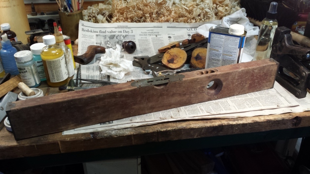
My dad died when I was still a teenager.  Unlike his father, who was a carpenter, my dad wasn’t much of a woodworker.  The few tools he left behind were mostly garden variety homeowner tools purchased from the local hardware store.  So when my brother gifted me my dad’s old level this summer, I didn’t give it much thought.  It was in horrible condition from decades of neglect.  I brought it home and with barely a glance, set it aside on my workbench to deal with later.

With cooler fall temperatures here on the east coast, I recently pulled it out for a closer look.  Upon closer inspection, I found that it is a Stanley no. 3 level, which was somewhat of a surprise in and of itself.   More interesting, the trademark stamp dates it to the 1890s, approximately 30-35 years before my dad was born.  It could have been my grandfather’s, but even he would have had to have purchased it as a teenager, if acquired new.  Of course there is no way to know where it came from or who originally owned it, but it ended up in my father’s hands, then my brother’s, and thanks to him, it now belongs to me.

As you can see from the quick shot I took before I got started on it, virtually all the original finish is gone and the wood faded from exposure to the elements.  It appears to have spent a good deal of time in a shed or barn.  The primary glass vial was intact and serviceable, but the plumb vial was broken long ago.  Otherwise, all the parts were in place and thankfully, the vial adjustment screws were not frozen.

Level Pre-Restoration

My dad’s 1890s vintage Stanley no. 3 Level, partially disassembled

I disassembled and removed all the hardware to better evaluate what needed to be done in terms of cleanup, and to assess the broken plumb vial.  After cleaning the rust off all the screws and the vial adjustment mechanisms, I cleaned the crud off the brass plates and end caps.  I never polish old brass hardware, but I decided in this case to clean off most of the oxidation in order to better see the center scribe line.

With the hardware cleaned up, I moved on to the wood.  Despite its condition, there were numerous paint specks and splatters from years of use that I wanted to protect.  The wood itself is evidently cherry.  I cleaned it lightly with Kramer’s Blemish Clarifier to remove any loose dirt and crud.  I then applied 6 or 8 applications of Kramer’s Best Antique Improver, which I’ve written about before.  It’s great stuff, all natural (no petrochemicals), and restores life to finished and unfinished wood.

In the meantime, I went to work sourcing a proper replacement vial.  I preferred to keep it as close to original as possible, so new acrylic vials were out of the question.  I found a few glass vials for sale on eBay, but the prices were absurdly high.  So, I started trolling for a suitable “donor” level of approximately the same vintage.  It took 2 or 3 weeks, but I finally found one for under $10 that had the plumb vial intact.  When it arrived, I was surprised to find the condition actually better than the photos reflected.  I actually felt a little guilty stripping it of one of its parts.

Plumb Vial Before Repair

Plumb Assembly Before Vial Replacement

Now if you’ve never replaced a vial in an old Stanley level, you might be surprised to learn that they used Plaster of Paris (or something similar) to cement the glass vial in the tube shaped holder.  This both held it in place and also protected the fragile ends.  Getting the vial out of the old plane was much easier than I anticipated.  Pulling the split holder tube open slightly, the vial and plaster slid right out in one piece.  Once out, the old plaster easily released from the glass vial.  The vial has a paper backing that wraps around the back side, but it isn’t attached.  So carefully removing that paper and setting it aside, a quick cleaning of the glass had it looking very much like new in short order.  Positioning the vial along with the paper backing into the assembly on my dad’s plane, I dabbed some plaster into place at each end and allowed it to dry.

I reattached all the hardware, and calibrated both vials using another level as a guide.  Completed, my dad’s old level is once again accurate and ready for the workshop.  You can just make out the replaced vial in the photo on the left.  Now, as to the donor level I bought, it’s still sitting here in need of a plumb vial.  There’s clearly something wrong with this scenario!

Complete Full ViewComplete Full View 2

A Lost Fragment of Joseph Moxon

Hysterical parody of Joseph Moxon by Christopher Schwarz; too good not to share!

http://blog.lostartpress.com/2012/10/15/a-lost-fragment-of-joseph-moxon/

Deconstructing the Wright Flyer

I spent this past week on vacation at the beautiful Outer Banks of North Carolina.  The OBX is one of my favorite places on earth, and I’ve been visiting just about every year for the past 30 years.  Despite its growth and development, especially over the last 20 years, there is still something raw about the Outer Banks.  Mother Nature may have yielded some of her land, but the spirit of the place is still very much wild, a precarious thin line of sand at the mercy of the Atlantic Ocean.  It was here, on the sandy dunes of Kitty Hawk and Kill Devil Hills back in December of 1903, that Orville and Wilbur Wright first flew a heavier-than-air craft under its own power.

Kitty Hawk CampSitting on a dune deck overlooking the Atlantic just a few miles from Kitty Hawk this week, I got to thinking about just what kind of tools the Wright brothers might have used when building the Wright Flyer.  The plane’s wings were constructed of spruce and ash covered with muslin.  The rest of the frame was metal, not at all surprising considering the Wrights were machinists, not woodworkers.  After all, they designed and developed the Flyer in their Ohio bicycle shop.  They favored coastal North Carolina for its windy dunes and because it was remote – competition for flight was intense and they didn’t want a lot of press at that point.

Fortunately, the construction of the plane has been exhaustively researched and documented, not a task as simple as one might assume since the Wrights were very secretive, didn’t keep detailed plans of the design, and constantly made changes on the fly (no pun intended). [1]  The plane’s framework “floated” within fabric pockets sewn inside, making the muslin covering an integral part of the structure. This ingenious feature made the aircraft light, strong, and flexible. The 1903 Flyer was powered by a simple four-cylinder engine of the Wrights’ own design.  To fly the airplane, the pilot lay prone with his head forward, his left hand operating the elevator control. Lateral control was achieved by warping the wing tips in opposite directions via wires attached to a hip cradle mounted on the lower wing. The pilot shifted his hips from side to side to operate the mechanism, which also moved the rudder. [2]

Wingspan: 12.3 m (40 ft 4 in)
Length: 6.4 m (21 ft)
Height: 2.8 m (9 ft 3 in)
Weight, empty: 274 kg (605 lb)
Engine: Gasoline, 12 hp
Manufacturer: Wilbur and Orville Wright, Dayton, Ohio, 1903

Construction

Wright Cycle ShopMy interest in the Flyer was centered on the woodworking tools and techniques that might have been employed.  However, in researching the Wrights, their shop, and the Flyer, it became clear that the woodworking aspect of the plane’s construction was incidental at best.  Obviously the focus (both then and now) was on the science – weight, power, aerodynamics, and control.  Records of their workshop reveals it was sparse with relatively few tools, and those tools they had were mainly dedicated to metal work.[2]  The bicycle shop had a 14″ Putnam Lathe, a 20″ Barnes drill press, and a 26″ Cresent bandsaw.   References confirming this are attributed to a book, “Charles Taylor, Mechanician.”  Taylor, of course, was the man who built the aluminum engine specifically for the Flyer.

Orville Wright at work in ShopThe propellers, wing struts, and wing framework were the only parts of the aircraft that were made of wood.  Since the Flyer was designed to be portable, joinery was all temporary and removable, using clips and brackets that were fabricated of metal.  In fact, it can be assumed that the decision to use of wooden components was probably based on practicality.  Orville and Wilbur wanted to keep the weight and cost down, and wooden parts were easy to replace if broken.  Lightweight metals like aluminum, which was used for the engine, were still comparatively expensive at the turn of the century.  Parts made of Spruce were strong, lightweight, and cheaply replaceable.

While I could not find any direct reference to the woodworking tools and techniques employed to make the wooden parts of the plane, looking at detailed photos of the components provides some insight.  With the exception of the propellers, which were hand carved, the rest of the parts were fairly simple and utilitarian in both design and execution.  Also, given the fact that the Wright Bicycle Shop was a metalwork business, and the Wrights were cheap about their outlay for tools and equipment, it’s safe to assume that the wooden components were formed using the most basic of woodworking hand tools – Saws, planes, spokeshaves, and chisels.

Wright Shop Tools

It turns out that, from a woodworking perspective, the most interesting component were the propellers.  As mentioned, the propellers were carefully hand carved to achieve the greatest possible efficiency.  The Wrights thought propeller design would be a simple matter and intended to adapt data from shipbuilding.  However, their library research disclosed no established formulas for either marine or air propellers, and they found themselves with no sure starting point. They discussed and argued the question, sometimes heatedly, until they concluded that an aeronautical propeller is essentially a wing rotating in the vertical plane. On that basis, they used data from more wind tunnel tests to design their propellers. The finished blades were just over eight feet long, made of three laminations of glued spruce. The Wrights decided on twin “pusher” propellers (counter-rotating to cancel torque), which would act on a greater quantity of air than a single relatively slow propeller and not disturb airflow over the leading edge of the wings.[3]

Wilbur Wright At Lathe c. 1897The propeller blade is shaped like an airfoil and there is a pressure difference created across the blade because of the motion of the spinning blade. The pressure difference causes large amounts of air to be accelerated through the plane of the propeller and the reaction of the vehicle to this motion generates a force called thrust. The thrust pushes the aircraft forward in accordance with Newton’s first law of motion.  The use of high speed (~350 revolutions per minute), thin propellers on their aircraft was one of the major breakthroughs for the Wright brothers and allowed them to succeed where others failed. At the time, others employed low speed, thick bladed propellers, much like the blades of a wind mill. But the brothers correctly determined that high speed, thin propellers are more efficient than low speed thick blades. [4]

Fortunately, the Wright Flyer was a far more impressive piece of engineering than it was an example of turn of the century woodwork.  Call it a little vacation inspired curiosity, but I enjoyed exploring this important piece of history this week.  If you’re lucky enough to visit the Outer Banks, I highly recommend a trip to the Wright Memorial National Park at Kill Devil Hills.  Following an afternoon at the park, make sure you drive down Collington Road to Billy’s Seafood, one of the area’s more recent national treasures.  Best steamed crabs on the beach!

Steamed Crabs

_______________________________________

1. The Wrights left an obscure trail to follow, carefully guarding their findings and working in secrecy. As a result, little is available in the way of blueprints, designs or instructions. – http://www.countdowntokittyhawk.com/flyer/2003/construction.html
2. National Air and SpaceMuseum, http://airandspace.si.edu/exhibitions/gal100/wright1903.html
3. Wikipedia http://en.wikipedia.org/wiki/Wright_brothers
4. Nasa, http://wright.nasa.gov/airplane/propeller.html

***


Corrugated Planes are Groovy, Baby!

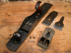
Stanley Bedrock no. 607C, c. 1911

Let me just put it out there right up front – I like corrugated planes.  Sure, their practical value is questionable.  I don’t care.  I like them, and all of the bench planes I use, as well as most of those in my humble collection, have corrugated soles.

Corrugations are a series of grooves milled into the sole of the plane.  Running front to back and spaced about 1/8″ apart, they stop short of the mouth at both the front and rear sections.  Introduced to the Stanley line of bench planes in 1898, corrugations were available on all sizes from the no. 2 through the no. 8, as well as the comparable sizes in the Bedrock series.  The no. 1 was never offered with a corrugated sole, and the no. 5-1/4 wasn’t introduced until 1921.  All the others, however, were available with corrugations and were distinguished from the plain versions by the suffix ‘C’ appended to the model number – nos. 2C, 3C, 4C, etc.  All the corrugated models were sporadically discontinued between the mid 1940s and mid 1960s.

While some argue that the feature was more a competitive marketing vehicle than a functional improvement, Stanley offered no explanation in its 1898 brochure, only stating “corrugated bottoms furnished without additional expense if so ordered.”  The reasoning most frequently accepted has to do with the vacuum created between two flat surfaces in contact with each other.  I’m no physicist, but I do know a little about science.  While this phenomenon is easily demonstrated with two sheets of glass, I have a hard time believing that wood is capable of creating much of a vacuum when in contact with something as small as the sole of a plane, even the large ones.

In my opinion, the reason why corrugations might work in theory is a simple matter of reduced friction.  Friction is defined as the resistance an object encounters in moving against another object.   Imagine that you are trying to push a plane across a board. If you apply a very small force, the plane will not move.  The frictional force between the two surfaces is greater than the force with which you are pushing the plane.  If the frictional force was less than the force you exert, the plane would slide forward.   So, in order to move the plane, you can do one of two things – reduce the frictional force of the plane against the board on which it sits, or push harder.

By milling grooves into the sole of the plane, Stanley reduced the amount of surface area that contacts the wood, the effect of which was to reduce the coefficient of friction between the two surfaces.  In theory, this should make a corrugated plane easier to push forward than one with a smooth sole.  This makes more sense to me than the theory of a vacuum created between the two surfaces, but I’m sure some will disagree.

Whether or not using a plane with a corrugated bottom provides a noticeably different experience to the average woodworker is debatable, but the idea clearly gained traction (no pun intended).  While less common than their flat soled brethren, corrugated versions were successfully sold for well over a half a century, and are still offered by some modern manufacturers today.

So here’s to corrugated planes… Easier to push or not, they’re groovy, baby!  Yeah!

Stanley No. 7 Reflects Secret History

Some months back I purchased a particularly beautiful old Stanley no. 7 jointer plane dating from the late 1880s with the intention of reselling it. It was sharp, clean from decades of proper care, and looked like it was still being used a week ago – absolutely amazing condition for its age. The original owner’s initials were neatly stamped on one side and it came from his family’s estate, which was sadly being liquidated. The plane was remarkably perfect by all accounts – except one…

At some point, almost certainly early in its life, the plane was dropped, breaking off the top quarter of the frog. In a classic reflection of those parsimonious times and testament to the care the owner gave to his tools, he went to unusual lengths to repair that frog, fabricating a perfectly fitting replacement section out of brass, secured with handmade copper rivets. Normally I shy away from tools with such repairs, but the complexity and care given to this one fascinated me. It was extremely well executed, having no doubt taken the better part of a day (perhaps even two) to complete, with an aesthetic effect that was detectable only upon close inspection. More important, it also returned the plane to perfect working order.

I was so conflicted I let the plane sit in my shop for weeks as I tried to decide what to do with it. Obviously treasured by its original owner, whether through necessity or nostalgia, it was used and handed down within his family for numerous generations. I hated to think of it being sold for scrap or parts after 130 years, especially given its impeccable working condition. Eventually reason and practicality prevailed, and I reluctantly decided to just list it at a fixed price on eBay, hoping I would find a buyer who could appreciate it as it was. And find a buyer I did… one with a surprising affinity for this particular plane.

Turns out the guy who bought it already had at least one other plane from the same estate with the same owner’s initials stamped on the side. He wrote and told me he was so intrigued at the care the owner had given his tools, he felt compelled to own this no. 7 just for the repair it featured. For him, the repair reflected the respect and value afforded the tool, and that little bit of history made it all the more desirable. He was excited to get it and I was thrilled to have found it a home with a new owner who ‘gets it’ – who appreciates that tool for the secret history it carries in an exceptionally well executed repair. You have to love that!