Rev-O-Noc Renewal

Rev-O-Noc 5C in pretty rough condition

I can count on one hand the number of planes I’ve refinished (vs. restored) over the years, but this Rev-O-Noc 5C jack plane had some issues that made an anti-rust dip and repainting the best course of action.

Disassembled for assessment

The entire body was a rustbucket with very little japanning remaining. The lever cap fortunately looked worse than it actually was, and while the cap iron was salvageable, the Rev-O-Noc iron had some pretty deep pitting on the business end. While I was able to sharpen through that, there was something off with the temper of the blade that I didn’t like, so I added a Vaughan & Bushnell iron I had on hand that’s better suited for use. The break in the tote was clean, so I epoxied it back together and then spent the better part of a week refinishing it to match the knob. The repair turned out really nice and is completely invisible.

Repaired Tote came out incredibly nice

HSB Rev-O-Noc was a store brand from Hibbard, Spencer, Bartlett & Co., a Chicago hardware dealership that formed in 1882, but whose origin dates back to at least 1855 in the form of Tuttle, Hibbard & Co. In 1932, the company introduced a new line of hand tools under the brand name “True Value” and by 1948, Hibbard’s annual sales reached nearly $30 million. Business slowed and profits shrunk, however, as new hardware cooperatives began to bypass traditional wholesalers. In 1962, the company’s owners sold both the hardware operations and the “True Value” brand to John Cotter for $2.5 million. Yes, that’s the True Value brand we know today.

Also interesting, the name Revonoc is the reverse spelling of Conover. Conover was the name of an officer of the company, and apparently had a separate hardware company prior to joining Hibbard, Spencer, Bartlett & Co. They used this backwards spelling of his name for their brand of planes sold by HS&B from about 1920-1940. They were made at times by both Stanley and Sargent, but this one is clearly Stanley made based on the casting, frog, and hardware.

As far as I can tell, this plane likely falls somewhere closer to 1920 given the short knob and small adjustment nut. Of course, it’s also possible it’s an earlier plane and the Revonoc blade was a later replacement. I just don’t know.

Despite a gnarly looking rust damaged sole, the mouth area was in decent shape and the plane functioned true to Stanley’s level of excellence. Once everything was cleaned up, oiled, reassembled, and tuned, this old plane shaved wood like a champ, producing some wispy thin shavings with no effort at all.

(Disclosure: This article contains paid links that help support the site)

Restoration completed, sharpened and tuned for use again

Don’t Strip or Dip! Scrape That Rust Away!

I read so many posts and articles online from guys doing absolutely heinous things to old tools. From chemical strippers to electrolysis, sanding to anti-rust dips, everyone has their own ideas about how best to remove rust. While any or all of these methods work, they’re all destructive on some level. I suppose that’s fine if your objective is to refinish the tool for use, but in my opinion it strips away all the character and beauty of the tool. Certainly some tools are so far gone there’s no other viable choice, but in many cases, there is a better way.

When I started collecting and restoring tools, I spent almost a year researching everything I could find on archival restoration and preservation, the techniques museums use. I didn’t want to simply refinish tools to make them appear new, I wanted to restore them to functional use while maintaining the aesthetic character that only decades of use and age can impart. My goal was (and remains) to bring them back to a point where they look and function as if they had been properly cared for over the years.

Like anyone else, my learning process came through trial and error. I quickly discovered that the anti-rust dips, while working well, left the metal with a dull and lifeless grey phosphate coating that I found unnatural and unappealing. Likewise, vinegar, citric acid, electrolysis, wire brushing, and sanding all do the job, but at the cost of all the color, character, and charm that makes old tools so appealing. What I really wanted to accomplish was to remove the rust while leaving (at least most of) the patina intact – that lovely brownish gray darkening of the metal that only comes from age and use.

Stanley no. 4C base, as found with considerable surface rust

I found that on many tools, specifically those that haven’t been exposed to overtly wet conditions, the rust is really only on the surface and in many cases hasn’t yet eaten into the metal, causing the cancerous pitting that we all despise. It has been my experience that often times a really gnarly looking rusty crust will come right off, leaving relatively undamaged metal that still retains that desirable patina below.

By using a 3 or 4 inch glass scraper with a very sharp blade, held at a fairly high angle, I slowly and carefully begin scraping the rust off the surface of the plane body. This does require a sharp undamaged blade. Once it gets knicks in the edge, it will start leaving light scratches in the underlying patina, which you don’t want.

It’s a slow and methodical process, but the payoff is worth the effort. As you can hopefully see in the photos above, there’s a distinct line where the rust is removed. You can also begin to see the underlying patina on the metal surface, and thankfully in this case, no pitting.

Scraping using the glass scraper

Once all the rust is removed, the metal surface will be dusty and dirty, and you may well see some micro-scratches from the scraper. I’ll take care of those in the next step.

Using a cleaner/degreaser, gently buff the surface with very fine steel wool (000 or 0000). You want to clean the metal, smoothing out and blending in any scratches in the patina without removing it. Careful here, as that patina is fragile. Go slow. Follow up with the cleaner/degreaser on a paper towel or rag until it’s completely clean.

Once clean and dry, I usually wipe it down with something to help protect and preserve it with Kramer’s Best Antique Improver. Howard’s Feed-n-Wax, Camellia oil, or Renaissance Wax, etc. will also work. Camellia oil, by the way, is really good stuff for protecting tools and knives, and is food safe. What you should be left with now is a clean surface free of rust, but retaining that beautiful patina.

The stanley plane body after cleaning, degreasing, and a wipe down with Kramer’s Best

With all the rust removed from the surface, you can see the underlying patina is still very much intact. Once the rest of the parts are cleaned and the plane reassembled, its beauty really shines through. I find this method of restoration produces superior results to any other I’ve found thus far. Mind you, it’s a workout! But that’s okay, too.

(Disclosure: This article contains paid links that help support the site)

Everything You Ever Wanted to Know About Stanley Bed Rock Planes

317 SBR605C Type 6 Post 1

Stanley Bed Rock no. 605C, Type 6, c. 1912-1921

History

The motivation behind Stanley’s decision to develop the Bed Rock line of planes is debatable. However, given their genius at marketing and creating demand, I suspect it was driven by a couple of different factors. In 1895, Justice Traut patented what would become the basic Bed Rock design. That same year, E. A. Schade patented the frog adjustment feature that would initially be used on the Bed Rock planes, and eventually (1907) would become a mainstay feature of the Bailey line of planes.

US536746-Traut Bed Rock0

J. A. Traut Patent 536,746, Apr 2, 1895

US545732-Shade Bed Rock

E. A. Schade Patent 545,732, Sept. 3, 1895

The introduction date of Bed Rock planes is a little uncertain. They first appeared in Stanley catalogs in 1900, but there is some evidence they may have begun manufacture as early as 1898. Apparently there was a dispute over the Schade patent, because those sold for the first year or two have the Sept. 3, 1895 patent date on the bed milled out.  This was done by the factory, and after the body had been japanned, indicating there was some sort of legal dispute over the Schade patent that required a last minute intervention prior to the planes being sold to the public.  By 1900, the milled out date was gone and just the single APR 2, 95 date from the Traut patent remained stamped into plane bodies until about 1911, when Stanley introduced a major design change.

Differences between Baileys and Bed Rocks

The Bed Rock line was marketed as Stanley’s premium line of bench planes. There were two primary differences between the Bailey line and the Bed Rocks, and both were in the frog design.

1. The mating surfaces of both plane body and frog was substantially larger than on the Bailey planes, and the frog on the Bed Rock fit into a groove on the body, eliminating any slop or shifting of the frog once in place. As Stanley described it in their marketing material:

The absolute solidity and one-piece effect of the “BED ROCK” PLANE is as much a fact as if the parts were all one, for the reason that the entire under surface of the Frog is in perfect contact with the solid seat cast in the Plane Bottom. The frog and the Bottom are so perfectly fitted together, that from the Plane Iron to the Bottom, the Plane is as one solid piece of metal. This form of construction positively prevents any chance of vibration.

2. Additionally, the Bed Rocks originally featured the frog adjustment mechanism that was patented by Schade on Sep. 3, 1895.  This same feature was eventually added to the Bailey line in 1907. Again, as described in a Stanley catalog:

The width of the mouth may be regulated and made wider or narrower as coarse or fine work may require. First remove the lever and cutter and loosen the two frog screws that fast en the frog t o it s seat. With a screw driver turn the center adjusting screw to the right to close the mouth, and to the left to open it. When the frog is in the position desired, tighten the frog screws and replace the cutter and lever .

Of course, there were other less significant differences as well. Interestingly, Stanley used the same numbering system for the Bed Rocks as the Baileys for the first 2 years of manufacture. It wasn’t until 1900 that the ‘600’ series of numbers (602 through 608) were cast into the plane bodies.  Stanley also had a Bed Rock branded lever cap that was used to help distinguish the two lines. The first design of this cap was marked ‘STANLEY’ on one line, then ‘R.&L.Co.’ on a middle line, with ‘BED ROCK’ on the bottom line. In 1908 the middle line was removed and caps were marked ‘STANLEY’ over ‘BED ROCK.’

Stanley Bed Rock no. 607 Type 3 c. 1900-1908

Stanley Bed Rock no. 607 Type 3 c. 1900-1908

Major Design Changes of 1911/1912

After the frog adjustment feature was added to the Bailey line in 1907, there was little to clearly differentiate the Bed Rock planes from the Bailey planes. For example, while the frog base design was arguably superior, it was a feature that was not readily apparent unless one were to disassemble the plane. Further, up until this point, the profile of the plane base was the same on both Bailey and Bed Rock lines; with both using the same classic ‘hump’ on each cheek. For Stanley to differentiate the two and justify the premium cost of the Bed Rock, it’s pretty easy to see the reasoning behind the changes they were about to make.

1. On March 14, 1911, Schade was granted another patent for the use of pins and set screws to both attach and adjust the position of the frog. This new design was superior to the previous (and the one provided on the Bailey planes), and set the Bed Rock line apart from all of Stanley’s competitors.

E. A Shrade Patent 987,081, Mar 14, 1911

E. A. Schade Patent 987,081, Mar 14, 1911

The Two Frog Attachment and Adjustment Designs

The Two Frog Attachment and Adjustment Designs

2. In addition to the new frog attachment and adjustment design, Stanley, in a move of marketing brilliance, also changed the profile of the body casting, flattening the tops of the cheeks to give the Bed Rock planes a unique look all their own. With such a clear visual distinction, it’s not hard to imagine that this decision was intended to induce those with the financial means to spend a little more and buy the premium Bed Rock planes.

3. The third major change was the addition of a raised receiver for the front knob, and the transition from the low knob to the high knob. It’s interesting that high knobs weren’t introduced to the Bailey line for another 8 years, and the raised receiver wasn’t added to the Bailey design until 1929, some 19 years later!

Miscellaneous

The Bed Rock line included pretty much the same assortment as the Bailey line, with the omission of a number 601, which was never produced. The line included everything else from the 602 to the 608, including half sizes and corrugated versions. The only other exception is that they never made a corrugated version of the 605 1/4.

Bed Rocks were slightly heavier planes with slightly greater mass. The 1934 Stanley catalog offers a comparison, with the no. 603 weighing 1/4 lb more than the Bailey no. 3, and the no. 608 weighing 1/2 lb more than the no. 8.

Prior to the 1911/1912 changes, Stanley manufactured Bed Rock style planes for both Winchester and Keen Kutter. These planes were very similar in design, varying mainly in the lateral adjustment levers, lever caps, and numbering system.

Bed Rock Flyer Bed Rock Flyer-1923

Bed Rock Type Study

The chart below is a summary Type Study of Stanley Bed Rock Planes based on Bob Kaune’s thorough 1996 study and additional research I have conducted over the past several years.   Please note that all type studies are approximate as production variations throughout the manufacturing years were quite common.   Also keep in mind that Type Studies are present day references, time-lines that map changes in the design and features of tools manufactured in the past.  Understand that neither Stanley nor any other manufacturer followed type studies.  They didn’t exist at the time.  In fact, it is only in the last 30 years or so that type studies have been assembled through historical research and the physical inspection of hundreds or thousands of tools made over the years.

Bed Rock Distinguishing Features By Type

Dates

Low Knob – Rounded Sides

Type 1 Beds marked with Bailey model numbers (Nos.2 to 8.)
Space below “PAT’D APR. 2. 95″ was milled out at the factory
S casting mark on bed (a single raised dot on some specimens)
Frogs & Lever Caps have “B” casting marks
Lateral lever has two patent dates “10-21-84 & 7-24-88”
STANLEY R & L CO…BED ROCK on lever caps, Q trademark stamp on most irons

1898

Type 2 7-24-88 is the only patent date on the lateral adjustment lever

1898-1899

Type 2a Model No.603 and 604 beds (only these two) were marked “No.60x”

1899

Type 3 All beds now marked with “600” numbers, i.e.; No.602 – 608
No milled space below “PAT’D. APR. 2. 95.” on bed, B casting marks
Frogs of some planes are nickel-plated on the machined surfaces

1900-1908

Type 4 B casting marks eliminated. No patent dates on the lateral adjustment lever
Lever caps now marked “STANLEY….BED ROCK”
Some irons have “S” trademark stamp, later planes have “T” trademark stamp

1908-1910

High Knob – Flat Sides

Type 5 Beds now marked “BED ROCK” in addition to “600” model numbers
2 patent dates behind frog, “PAT’D. APR. 2. 95″ & APR. 19. 10″
Flat-top sides introduced for first time
Raised knob receiver (flat version), Tall knobs introduced, “T” tm on irons
Frogs are now attached to beds with adjustment pins and set screws

1911

Type 6 Lever caps now marked “BED ROCK”
Irons stamped with “V” trademark or “X” trademark stamps

1912-1921

Type 6a 1-1/4″ diameter frog adjustment wheel
Iron stamped with “Y” Trademark (1922-1923)

1922

Type 7 One patent date behind the frog – “U.S. PAT. APR. 19. 10.”
Lever caps marked “STANLEY” only in the notched rectangular logo
Irons stamped with “AA” Trademark (1923-1935)

1923-1926

Type 8 Bed now stamped “MADE IN USA” in addition to the one patent date
Knob receiver boss now cupped for fitting knob

1927-1930

Type 9 Beds no longer have a patent date; stamped “MADE IN U.S.A.” only
Some lever caps nickel-plated with orange paint behind STANLEY logo

1931-1932

Type 10 Beds of No.603, 604 & 605-1/4 planes have raised handle receivers
Some frogs have orange paint on sides like Bailey planes
Lever caps now have kidney-shaped bolt holes
Irons stamped with BB tm starting in 1936

1933-1941

Type 11 Castings are heavier and thicker during war production years
Finishes left rough; lever caps not plated or polished

1942

Type 12 Frog adjustment nut either hard rubber or small diameter steel
Knob and handle are hardwood (maple) with dark varnish stain
All brass parts eliminated during war-time production
END OF PRODUCTION FOR BED ROCK PLANES

1943

The chart below lists specifications for Stanley’s line of Bed Rock planes.

Plane No. Dates Made Iron Width Length Weight
No. 602 1898-1942 1 5/8 7 2 lb 4 oz
No. 602C 1898-1923 1 5/8 7 2 lb 4 oz
No. 603 1898-1943 1 3/4 8 3 lb 4 oz
No. 603C 1898-1935 1 3/4 8 3 lb 4 oz
No. 604 1898-1943 2 9 3 lb 12 oz
No. 604C 1898-1935 2 9 3 lb 12 oz
No. 604 1/2 1898-1935 2 3/8 10 4 lb 12 oz
No. 604 1/2C 1898-1935 2 3/8 10 4 lb 12 oz
No. 605 1898-1942 2 14 4 lb 8 oz
No. 605C 1898-1935 2 14 4 lb 8 oz
No. 605 1/4 1925-1943 1 3/4 11 1/2 4 lb
No. 605 1/2 1898-1935 2 1/4 15 6 lb 8 oz
No. 605 1/2C 1898-1937 2 1/4 15 6 lb 8 oz
No. 606 1898-1941 2 3/8 18 7 lb 6 oz
No. 606C 1898-1934 2 3/8 18 7 lb 6 oz
No. 607 1898-1943 2 3/8 22 8 lb 12 oz
No. 607C 1898-1935 2 3/8 22 8 lb 12 oz
No. 608 1898-1940 2 5/8 24 9 lb 12 oz
No. 608C 1898-1935 2 5/8 24 9 lb 12 oz

_________________________________

References

Kaune, Bob, Bed Rock Type Study, 1996

Sellens, Alvin, The Stanley Plane, 1975

Smith, Roger, Patented Transitional & Metallic Planes In America, Vols. I & II, 1992

Walter, John, Stanley Tools – A Guide to Identity & Value, 1996

Various Stanley catalogs, flyers, pamphlets

Solving Those Pesky Blade Depth Frustrations

New users of hand planes frequently have trouble figuring out just how to get the iron (blade) to fit through the mouth on the plane’s body. I get this question in both emails and I also see it reflected in the search parameters for those who visit the site. The challenge is to get everything set so the iron extends through the mouth without jamming up at the front of the opening.

Well fear not, for here is a simple illustrated guide to getting it done quickly and hopefully without frustration!

There are basically 5 things that have to be set correctly in order for shaving wood to begin:

  1. The iron must be attached to the cap iron correctly, with the cap iron attached to the flat unbeveled side of the iron. This may very well be the greatest cause of problems. The cap iron should be positioned to within about 1/32″ to 1/16″ of the cutting edge of the iron. (Figures 1 and 2)
  2. The frog must be positioned correctly, neither too far forward or too far toward the rear.  There’s room for adjustment, of course, but it’s a good idea to start with it aligned with the rear edge of the mouth. You can then move it forward to fine tune the cut as appropriate. (Figures 3 and 4)
  3. The iron and cap iron assembly (once screwed together) must be positioned absolutely flat against the face of the frog. You may have to jiggle it around a little to make sure it falls into place over the frog’s adjust yoke. (Figure 5)
  4. The Lever Cap must be set with enough pressure to hold the iron firmly, but not so tight that the depth adjustment can’t work. There’s a sweet spot there, you just have to find it through trial and error.
  5. Use the lateral adjustment to align the cutting edge so it’s parallel to the mouth opening. In some cases you may have to tap the edge of the iron a little to get into a workable position. I use a small brass hammer so as not to mushroom the edge of the iron, but it’s not critical. (Figures 6 – 8)
Figure 1 - Note the cap iron is attached to the Unbeveled side of the iron

Figure 1 – Note the cap iron is attached to the Unbeveled side of the iron

Figure 2 -

Figure 2 – View from the bottom, the attachment screw should be on the same side as the iron’s beveled edge

Figure 3 - Loosed the frog bolts (blue arrow) and position the frog so it aligns with the rear edge of the mouth (red arrow)

Figure 3 – Loosen the frog bolts (blue arrow) and position the frog so it aligns with the rear edge of the mouth (red arrow)

Blade Set 4

Figure 4 – Stanley planes made after 1907 have a frog adjustment screw, which is used to easily fine tune the position of the frog.

Blade Set 5

Figure 5 – Ensure the iron seats flush against the face of the frog

Figure 6 - The edge of the iron should extend over the mouth opening as shown

Figure 6 – The edge of the iron should extend over the mouth opening as shown

Figure 7 - Viewed from the bottom, the iron when retracted should look like this

Figure 7 – Viewed from the bottom, the iron when retracted should look like this

Figure 8 - As you turn the big brass adjustment knob, the iron will move forward and extend down through the mouth opening just enough to shave wood!

Figure 8 – As you turn the big brass adjustment knob, the iron will move forward and extend down through the mouth opening just enough to shave wood!

Note that if you’re doing fine finishing work you may need to go back and move the frog forward slightly to reduce the space between the front of the mouth opening and the cutting edge. This space should approximate the thickness of the shavings you expect to produce, so it’s typically very small on smoothing planes, while a little larger on jointer and fore planes.

Hopefully this provides answers to questions and solves one of the initial frustrations when using hand planes for the first time!

***


Plane Restoration for Use – Extreme Salvage Edition

Let’s face it, not all planes and tools are salvageable.  Sometimes, the neglect and decay is so extreme that the best you can do is pilfer them for parts. Other times, the tool can be saved, but nothing short of a full refinishing effort is in order. As anyone who reads this blog will know, my principled philosophical approach is one of preservation, to retain as much of the original finish and character of the tool as possible. I focus the majority of my time and effort on tools that are good candidates for that sort of conservative preservation methodology. However, there are tools that occasionally cross my path that require a heavier hand.

In this post, I will detail one of the many methods you might employ to restore a heavily rusted plane for use. I found this Stanley no. 4 on eBay for around $10 plus shipping. It’s a Type 19, dating from the 1950s, and as you can see from this eBay auction photo, was in horrible condition.

SB4-T19 ebay

Stanley No. 4 – eBay Auction Photo

And here’s a shot I tool myself before beginning the restoration. As you can see, it actually looked a little better that the eBay photo indicated. Just a little…

SB4-T19 Rest1

Photo taken just before restoration

As with any restoration, the first step is complete disassembly.

SB4-T19 Rest2

Plane completely disassembled

With heavy rust like this, I used a razor blade scraper to remove as much of the surface crud as possible. I started with the iron and cap iron, then continued with the plane body and frog face.  With a little care, this can be accomplished without scratching or gouging the surface of the metal, and it’s amazing how much of the rust you can remove. You can see in the photo below the effect of having scraped the right half of the cap iron, and the lower three quarters of the iron.

SB4-T19 Rest3

Note the contrast of scraped vs. unscraped metal

Here’s a close up. Note the difference. The nice thing about this is virtually all of the patina remains on the surface of the metal. You can leave it this way if you prefer, or continue on as I will show in the next step.

SB4-T19 Rest4

Close-up showing the scraped and unscraped iron and cap iron

Since this was a later model Stanley (less valuable) and destined for shop use, I decided to scrub it down to a clean surface, removing all traces of rust, corrosion, and subsequently age and patina. There are several ways to go about it at this point (chemical anti-rust agents and electrolysis for example), but I decided to stick with doing it the old fashioned way – elbow grease. Using 220 grit sandpaper lubricated with WD40, I scrubbed down all the exposed surfaces. The light oil really softens the effect of the sandpaper, greatly reducing any visible scratches.

SB4-T19 Rest9

Oil sanding using 220 grit wrapped around a wood block

The screws, nuts and hardware were brushed using a soft steel 6″ brush on my bench grinder. Finally, everything was scrubbed using a general purpose cleaner. Low and behold, the japanning on the bed was actually quite good under all that crud.  I finished up by using an citrus degreaser (not shown in the photos). As you can see, the difference from where I started is pretty striking.

SB4-T19 Rest10

Big difference, huh? This is starting to look like a plane again.

I don’t like my brass components highly polished. I used oil lubricated steel wool and a small steel brush to clean them up for this plane. The lighting in the “after” photo makes the brass look a bit brighter than it actually was.

SB4-T19 Rest12

Brass before cleaning

SB4-T19 Rest13

Brass after cleaning

The final consideration is the hardwood tote and knob. Much of the original finish was gone and what remained was in bad shape. I lightly sanded the entire surface, applied a gel stain, and when dry, topped it with a couple of coats of varnish.  Once completely dry and cured, I polished it up using paste wax.

SB4-T19 Rest14

Tote and knob in original condition

After refinishing

After refinishing

With all the parts refinished and restored, the iron was sharpened and the plane reassembled and tuned for use. Naturally it doesn’t have the charm of a Sweetheart era, or even the character of a fine condition 1950s vintage, but this plane was saved from the landfill and with proper care, can easily shave wood another 70+ years.

SB4-T19 Rest16

SB4-T19 Rest17

***

Setting Up a Stanley Gage Plane

Stanley Gage Plane - Frog and Iron Assembly

Stanley Gage Plane – Frog and Iron Assembly

Stanley Gage planes are a little finicky to set up initially, but once you get them set accurately, they do tend to stay that way.  The main benefit of the design is such that once properly set, you can remove the lever cap, iron and cap iron, and then replace them again, returning to the exact depth adjustment at which you had it set initially.  Further, since the iron/cap iron is positioned via an indexing block, there is no slop (movement) from side to side, and therefore no need for a lateral adjustment mechanism.

Indexing Block on Gage Iron

Indexing Block on Gage Iron

Some people will tell you that in order for the design to work, the cutting edge of the iron must be perfectly perpendicular to its edges.  Ideally, that is true.  However, I don’t think it’s actually all that critical.  What does need to be perpendicular to the cutting edge is the sides of the indexing block, which can be loosened and adjusted via the screw on the top side of the iron (show here on the left).

The indexing guide itself, which is attached to the lever cap, is not laterally adjustable, so in order for the iron to extend properly through the mouth of the plane, the iron’s edge needs to be perfectly aligned.  As I said, you ideally want everything to be at perfect right angles, but that’s not always what you end up with. By adjusting the indexing block so that it’s properly aligned in conjunction with the cutting edge on the iron, even a skewed edge can be aligned properly.

I admittedly don’t have a lot of extensive personal hands-on experience with the Gage planes.  I’ve owned a couple, and right or wrong, here’s how I set them up for use:

  1. Remove the lever cap and set it aside.
  2. Loosen (slightly) the indexing block that’s attached to the iron, just enough so it moves independently against the iron.
  3. Put the iron in place (seating the indexing block to engage the depth adjustment).
  4. Align the iron with the mouth opening, and carefully tighten the screw on top of the indexing block.
  5. Put the lever cap in place and tighten it.  You should be good to go.

***

Stanley Gage Planes – History and Type Study

John Porcius Gage formed the Gage Tool Co. in 1883, and operated it until 1917, making wood bottom transitional planes. J.P. Gage registered plane patents on 4 August 1885, 13 April 1886 and 8 November 1892. The 30 January 1883 patent of David A. Ridges was also used.

US339872-Gage-Patent

J. P. Gage Patent Drawing

The Gage “self-setting” design eliminated the need for a lateral adjustment feature, which eliminated slop in the blade movement. The adjustment slide was designed to accurately fit into a groove in the frog, and depth adjustment was controlled by a screw at the rear of the frog, similar to a low angle block plane. The two-piece lever cap design also functioned as a chipbreaker. The outer part of the cap serves as the lever cap, with the inner piece functioning as a chipbreaker. The mechanism is adjustable via a two-screw slide to bring it closer to the edge of the blade. The self setting feature allowed the cutter and cap to be removed and reinstalled without adjustment of the cut.

In 1919 Stanley Rule & Level Co. bought the Vineland NJ company, mainly to get the patent for their excellent frog design and to compete with Sargent’s Auto-Set line of planes that are very similar in both appearance and design. Stanley retained the use of the Gage name, producing a line of transitional planes from 1919 to 1935, and metal Gage planes from 1919 to about 1941, when the line was phased out.

The original Stanley Gage line of metal bench planes was numbered 3 through 7, sizes that compared to their Bailey counterparts. The G prefix was added in 1930 to distinguish them from the Bailey line (G3 through G7C). There were 10 different numbers included in the offering, which included corrugated versions that, like Bailey planes, were differentiated with a C suffix appended to the model number (ex. G3C or G7C).

Gage Plane

Stanley Gage no. 5, Type 2 (1924-1930)

Gage Type Study

There are four “Types” of Stanley Gage planes, which are thankfully far less complicated than most of the other Stanley Type studies.

Type 1 (1919-1923) – Plane beds marked “Pat. Appl’d For” in the casting. No “G” prefix to the model number

Type 2 (1924-1930) – “Pat. Appl’d For” removed from the casting. Plane beds are now marked with Schade’s 2-17-20 patent date.

Type 3 (1930-1941) – The “G” prefix added to the model number.

Type 4 – Same as Type 3 but has “Made in USA” added to the casting. (exact date of this is uncertain)


Sellens, Alvin, The Stanley Plane,: A History & Descriptive Inventory, Augusta, KS: Allvin Sellens, 1978.

Walter, John, Stanley Tools: Guide to Identity & Value, Marietta, OH: John Walter, 1996.

***

The 5 Hand Planes Everyone Should Own

Unless you live in a city apartment, or happen to be wealthy, disinterested, or lazy enough to pay someone to do all of your home maintenance projects, chances are now and then you have need of a hand plane.  Even the most ardent power tool minded woodworker can’t escape the reality that some jobs are just easier solved by a couple of passes with a hand plane than with anything you plug into an electrical outlet.   Whether you’re an active hand tool user, a neophyte learning to work wood by hand, a weekend woodworker or a casual homeowner, a basic set of good hand planes is essential.

There’s a great deal of generalization that goes into compiling a list like this.  Because hand planes tend to be used for specific applications, some woodworkers my find greater utility in some planes than others.  Someone who makes musical instruments would obviously need different tools than a furniture maker.  But speaking in the broadest sense, these are the 5 essential hand planes that virtually everyone should own.  Certainly for anyone interested in acquiring a first set of planes to use around the shop, farm, or house in the suburbs, these tools offer the greatest utility and versatility.

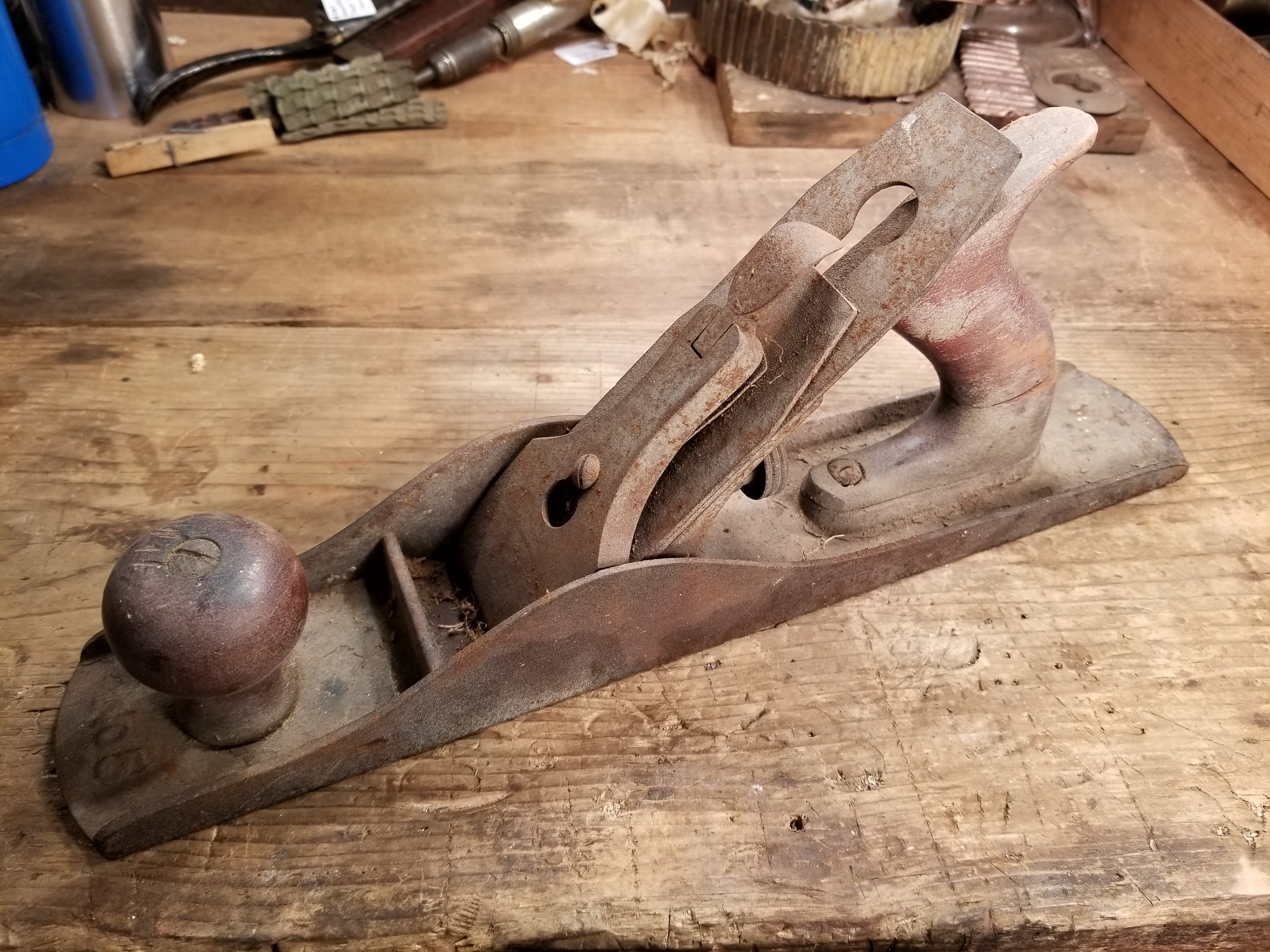
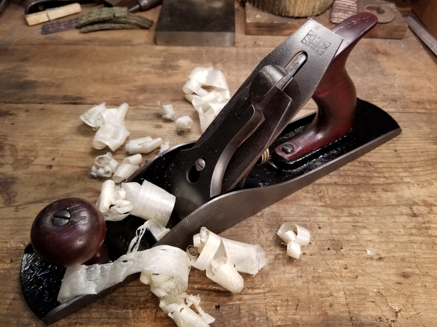
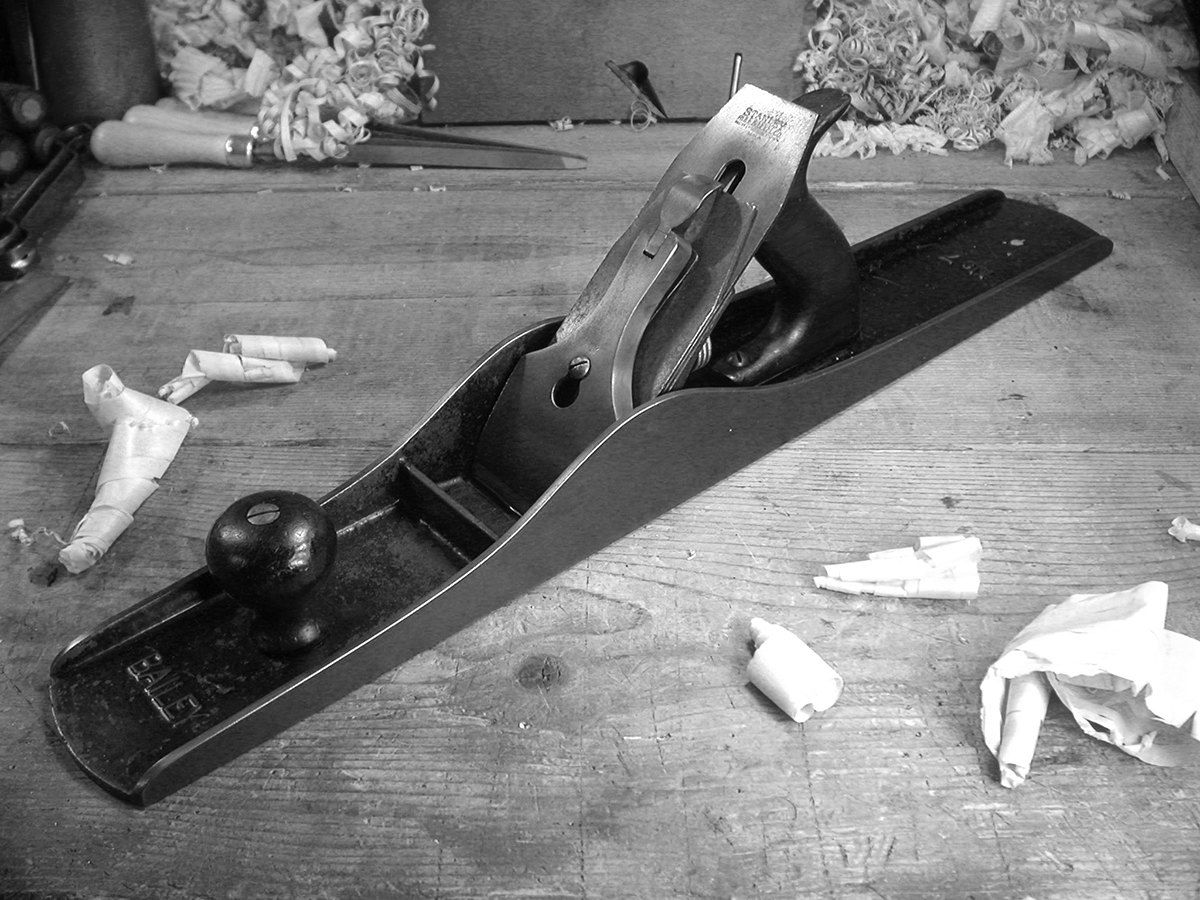
1. Fore Plane – The Stanley No. 5

Stanley Bailey No. 5, Type 11 (c. 1910-18)

Stanley Bailey No. 5, Type 11 (c. 1910-18)

Fore planes are those ranging from approximately 14 inches to 18 inches in length. In the Stanley bench plane assortment, these include the nos. 5, 5-1/4, 5-1/2, and 6. The term ‘Fore’ dates back several hundred years and is generally assumed to be a contraction of ‘Before’ and interpreted as the plane used first in flattening a surface. “It is called the Fore Plane because it is used before you come to work either with the Smooth Plane, or with the Joynter.” [1]

As the first plane one would use in preparing a surface, the Fore plane takes the most aggressive cut, removing rough saw marks and leveling out low and high spots, etc. The iron is sharpened with a significant camber, or curvature to the cutting edge, with as much as 1/16″ to 1/8″ difference between the center and the edges. This removes the most waste, but subsequently leaves the surface of the wood with a scalloped finish.

While either the Stanley no. 5 or no. 6 will do, the no. 5 is the better choice in our 5 plane roundup. Rough planing is a very physical activity, and the lighter weight of the no. 5 makes it less fatiguing to use. It’s smaller size also makes it more appropriate for the wide variety of other day to day planing jobs that most people likely face. The no. 5 is, in my opinion, the most versatile of all the bench planes and the plane I use most often.

2. Try (or Jointer) Plane – The Stanley No. 7

Stanley Bailey No. 7, Type 10 (c. 1907-09)

Stanley Bailey No. 7, Type 10 (c. 1907-09)

Try planes, more commonly known as Jointer planes, are those over 18 inches, and are most commonly 22 to 28 inches. Stanley’s offering of Jointer planes are the no. 7 and no. 8, measuring 22 inches and 24 inches respectively.As the name implies, a Jointer plane excels at truing the edges of long boards that will be glued together to make table tops, shelves, and carcasses. But its value and place on the workbench isn’t limited to edge work. The Try, or Jointer, plane is used to flatten and refine the surface left by the Fore plane. Its extra length allows it to true large flat surfaces without riding up over the peaks or dipping down into the valleys created (or left uncorrected) during the initial surface preparation.

Despite its heft, the Jointer should be considered a precision tool. The iron should be sharpened with a slight camber (or perhaps none at all if used exclusively for edge work), and the frog typically adjusted with a fine set for thinner shavings than the Fore plane. Working both across the grain and in all directions, the Try plane leaves a perfectly flat surface that requires only final touch up with the Smoothing plane.

Your choices between the two standards, nos. 7 and 8, are really a matter of personal preference. In this case, Newton’s laws of motion lend a helping hand.  The greater heft is actually a benefit, in that once you get it moving the additional mass helps keep it going with less effort. That said, the no. 8 is quite a beast, and my personal preference is for the lighter and shorter no. 7, which I find easier to manage.

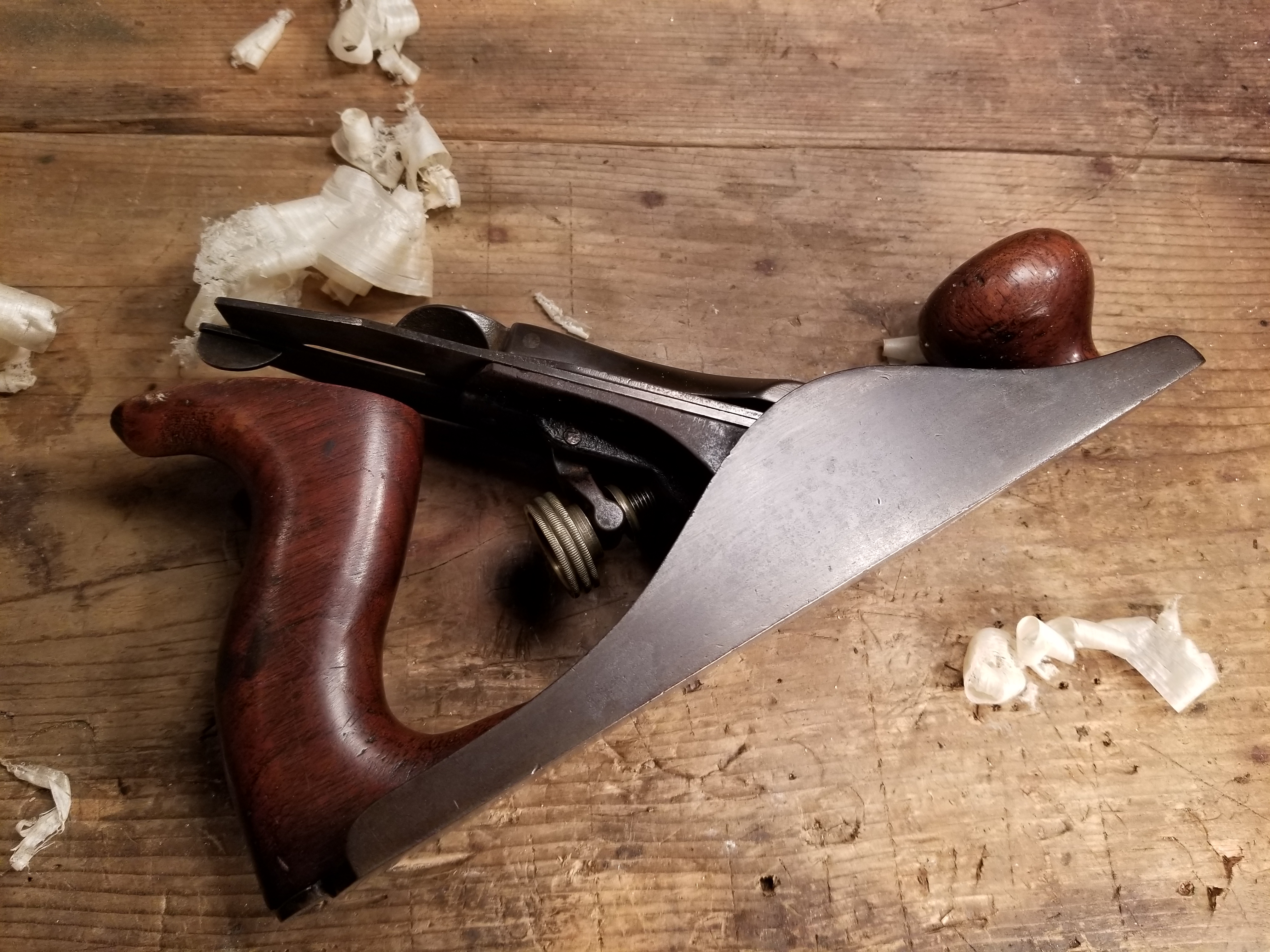
3. Smoothing Plane – The Stanley No. 4

Stanley Bailey No. 4C, Type 10 (c. 1907-09)

Stanley Bailey No. 4C, Type 10 (c. 1907-09)

Smoothing planes include the shorter planes in the lineup, those 10 inches or less. Stanley made a number of planes in this range, from the tiny no. 1 to the most popular no. 4 and its wider sibling, the 4-1/2.The Smoothing plane is the final plane used prior to applying the finish. Executed properly, there should be no need for sandpaper. Used primarily with the grain, the Smoothing plane is normally sharpened with just the slightest camber or left straight with its corners eased to prevent them from digging in or leaving tell tale ‘lines’ along the edge of the cut. The frog is adjusted with a closed mouth for the finest of cuts, and the shavings produced are tissue thin, ideally produced from long strokes covering the full length of the wood. Aside from perhaps a little hand scraping here and there, the surface left by the Smoothing plane should require no further treatment. In fact done correctly, sanding would actually diminish the quality of the surface left by the Smoother.

More so than with the Fore and Try planes, the choice of which size Smoother is really a matter of and comfort and the scale of your work. All of them will do a comparable job, although the nos. 1 and 2 are really only suited for very small surfaces (and very small hands). The no. 4 is considered the most versatile size, and the one I use most often. However, I do have a smaller no. 3 and a wider no. 4-1/2 that I reach for, depending on the size of the project. But since the point of this article is to identify the three core bench planes you’ll need for woodworking, the no. 4 is probably the best overall size choice for a single Smoothing plane for most people.

4. Standard Angle Block Plane – The Stanley No. 18 

Stanley Bailey No. 18, Type 17 (c. 1947-50)

Stanley Bailey No. 18, Type 17 (c. 1947-50)

This is my go-to block plane for everyday use, the one I always seem to grab first.  Mine is a very pristine WWI era model that I’m pretty sure I’ve used more than anyone else in its history.  Although it’s almost 100 years old, it looks like it could have been manufactured last year.  Both the japanning and nickel plating are pushing 100%, and so I baby it.

The Stanley no. 18 is a standard angle plane, meaning the iron is seated on a 20 degree bed.  With a bevel angle sharpened at the standard 25 degrees, you have a cutting angle of 45 degrees, same as a bench plane.  It also has an adjustable throat plate, an essential feature in a block plane.  The no. 18 is 6 inches long and fits my hand better than its longer, otherwise identical 7 inch brother, the no. 19.  And unlike the more popular Stanley no. 9-1/2, it feels more like an extension of my hand.

The no. 9-1/2 plane predates the no. 18 by about 15 years, was in production longer, and was the best selling block plane Stanley ever made.  It’s still made today, in fact, although the current design features a completely different mechanism from the original.  Admittedly, the no. 9-1/2 was the more popular of the two.  I truly don’t know why, though, since the design of the no. 18′s knuckle cap was far superior to the hooded lever cap on the no. 9-1/2, and it’s also more comfortable to hold in the hand.  I also find that the hooded cap on the no. 9-1/2 is more prone to slip around a little in use.  Not so with the no. 18.

Ironically they are both basically the same plane with two different styles of lever caps.  Other than the lever cap and its mounting bolt, all the other parts are interchangeable. Stanley charged a little more for the no. 18 and marketed it as virtually indestructible.  This of course was not true, for while the steel cap is arguably more durable, the bodies of both were cast iron and therefore susceptible to breaking if dropped.

I have several vintages of both models in my collection, but find the no. 18 with the knuckle cap superior in both function and comfort.  I use this more often than any other block plane I own.

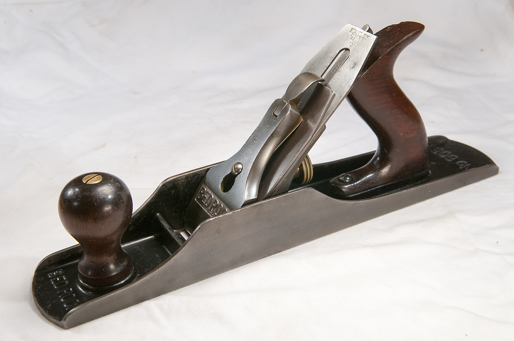
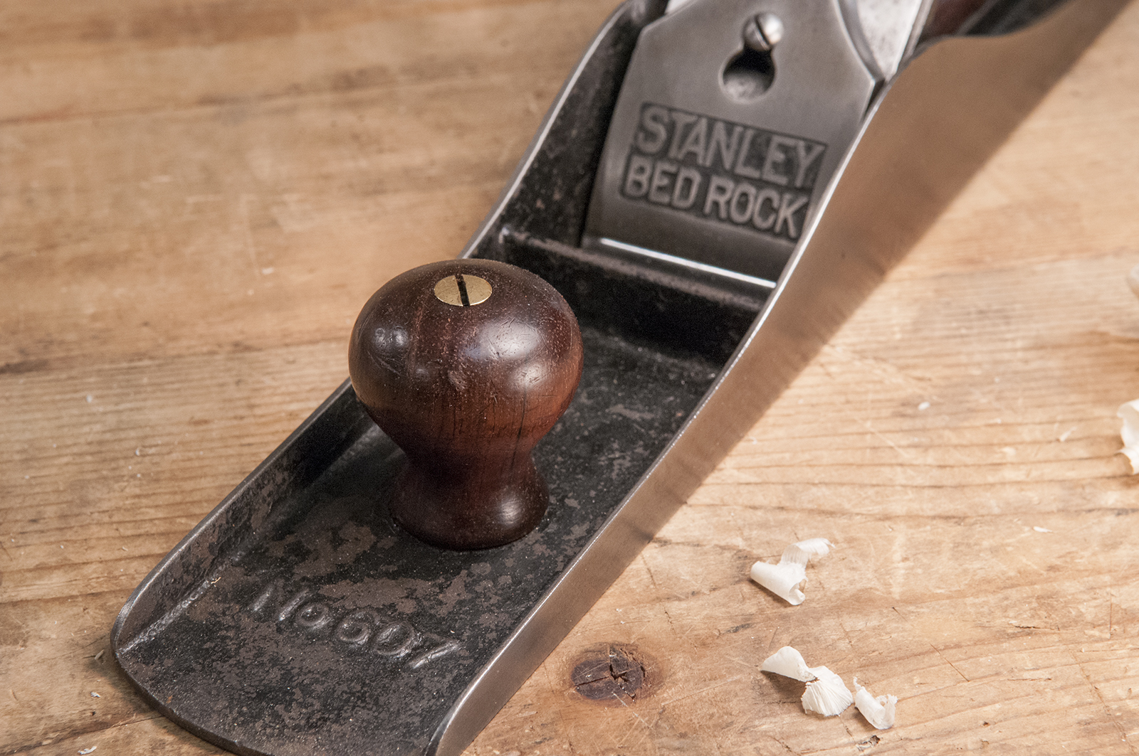
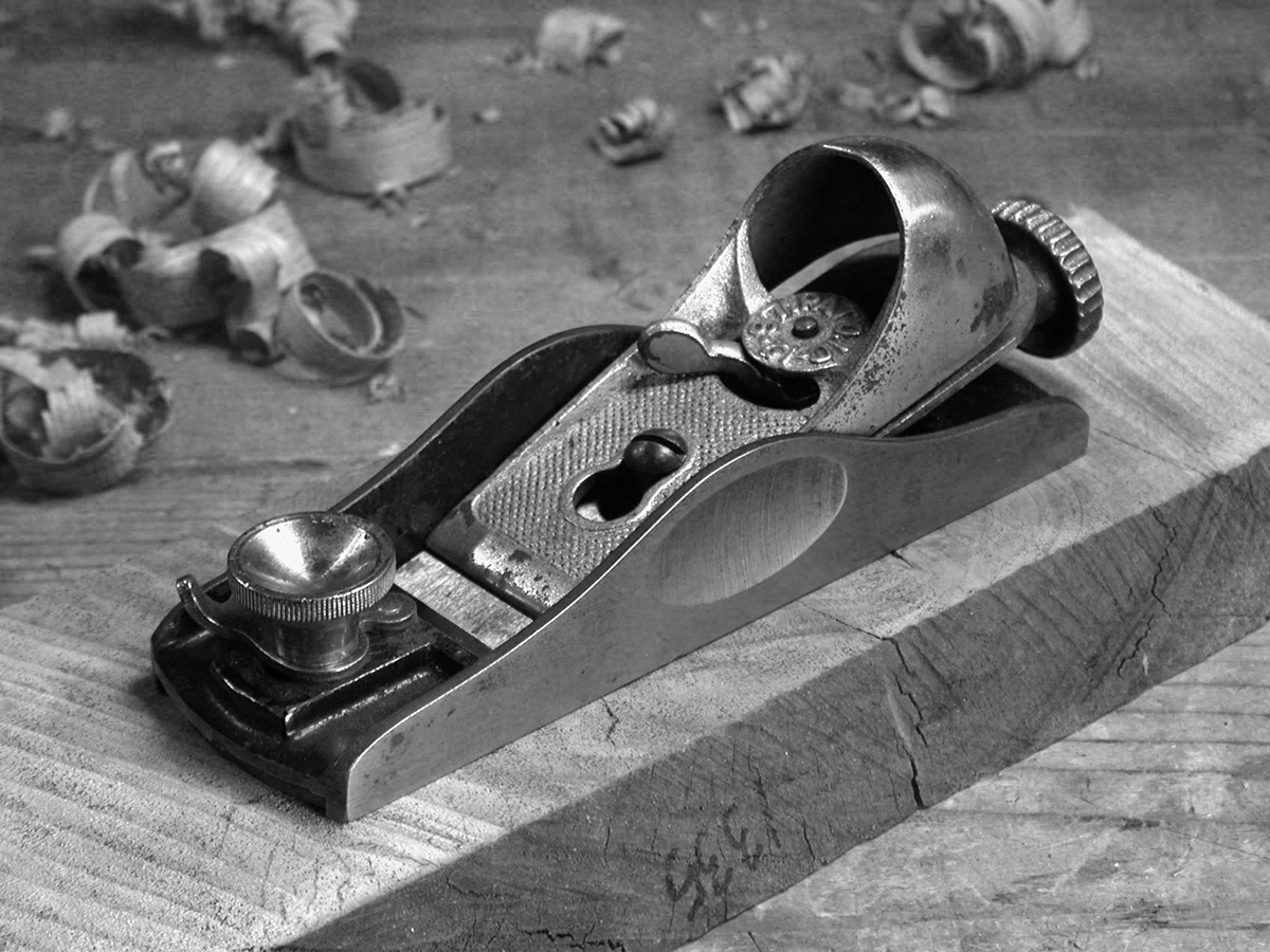
5. Low Angle Block Plane –  The Stanley No. 60 

Stanley Bailey no. 60 Type 2 (c. 1901-04)

Stanley Bailey no. 60 Type 2 (c. 1901-04)

The Stanley no. 60 (and the identical japanned version 60-1/2) is a low angle plane, meaning the iron is seated on a 12 degree bed.  Sharpened at 25 degrees, you have a cutting angle of 37 degrees.  The primary advantage of the lower angle of attack is that it excels at shaving end grain.

Like the no. 18, the 60 series of planes are approximately 6 inches long.  However, the 60 series are narrower with an iron width of 1-3/8 inches, vs the 1-5/8 inch irons on the standard angle planes, and the 60 series feature a narrower version of the hooded lever cap used on the no. 9-1/2.  The 60 series planes also have adjustable throat plates.

Low angle planes are typically used for cutting end grain, i.e., across the end of a cut, verses cutting along the grain, down the side of the wood.  The lower angle is perfect for the shearing action needed to cut those end fibers.  On cuts that will be visible and finished, this produces a very clean and smooth surface, whereas if left as cut from the saw, the grain tends to be very rough and porous.

On both standard and low angle block planes, the iron is seated bevel up, whereas on bench planes the bevel is usually down. There is a tremendous advantage with bevel up irons in that the angle of the bevel can be changed to affect a change in the angle of cut.  While there is more to consider in edge geometry than just the angle of cut (durability), you could reasonably sharpen the bevel on a low angle plane iron to 33 degrees and end up with an angle of cut of 45 degrees (12+33=45), the same as on a standard angle plane.  However, to accomplish a low angle of cut using a standard angle plane, you’d have to sharpen the bevel at a very shallow 17 degrees (20+17=37).  Durability of such a thin cutting edge would be problematic with most woods.

For this reason, along with a few others, many people consider the low angle plane to be the more versatile of the two. I tend to agree.  While I use my standard angle plane more often, if I could only have one block plane, it would have to be a low angle.

***

For more detailed information on the three step process using hand planes, I highly recommend you check out Christopher Schwarz’s outstanding Course, Medium, and Fine, available on DVD.

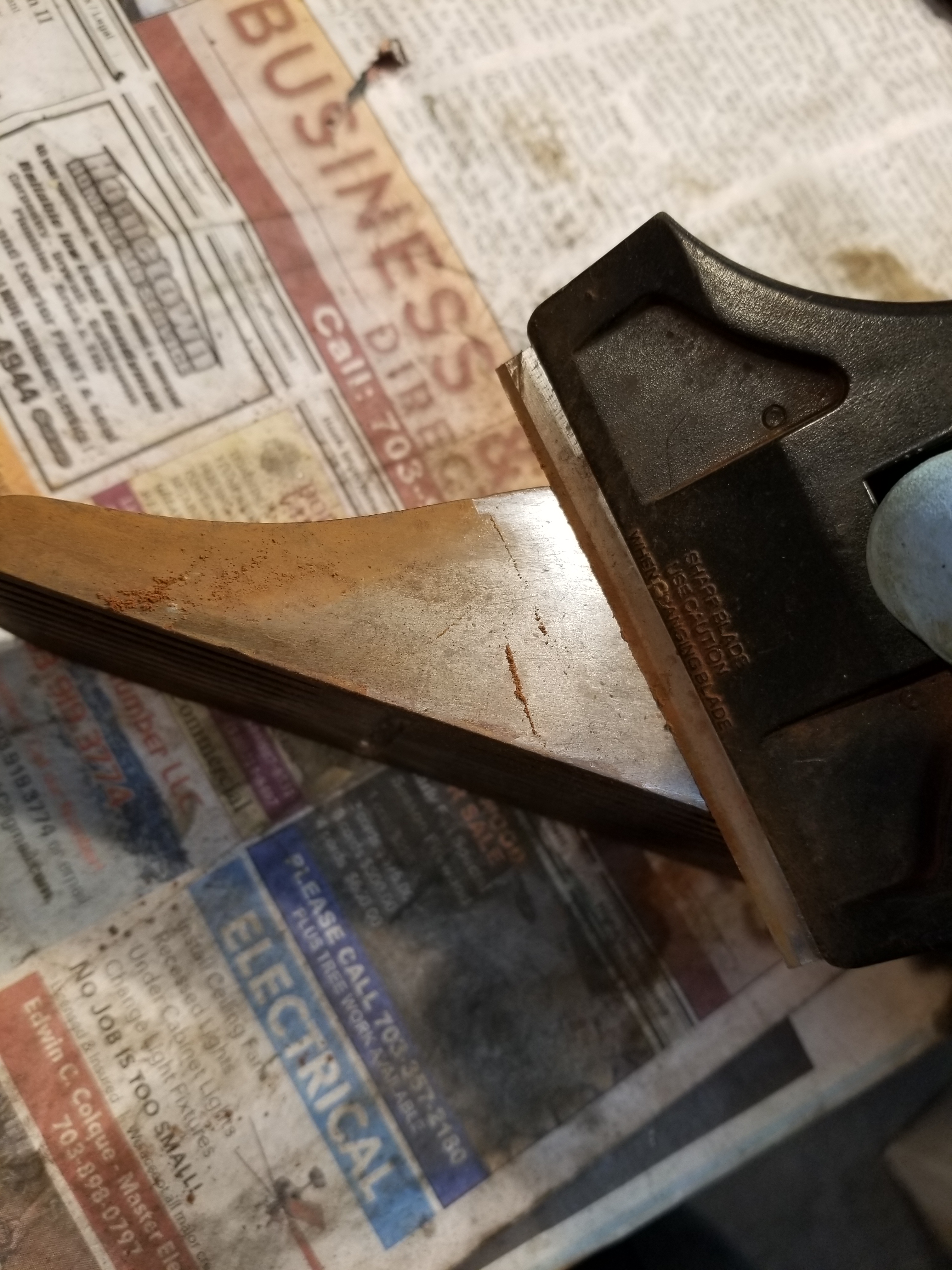
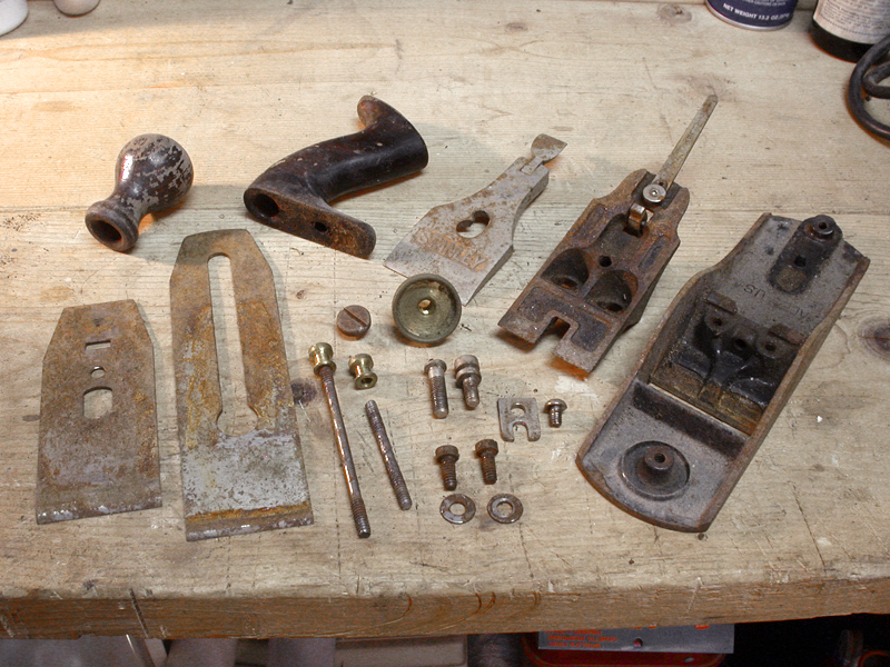
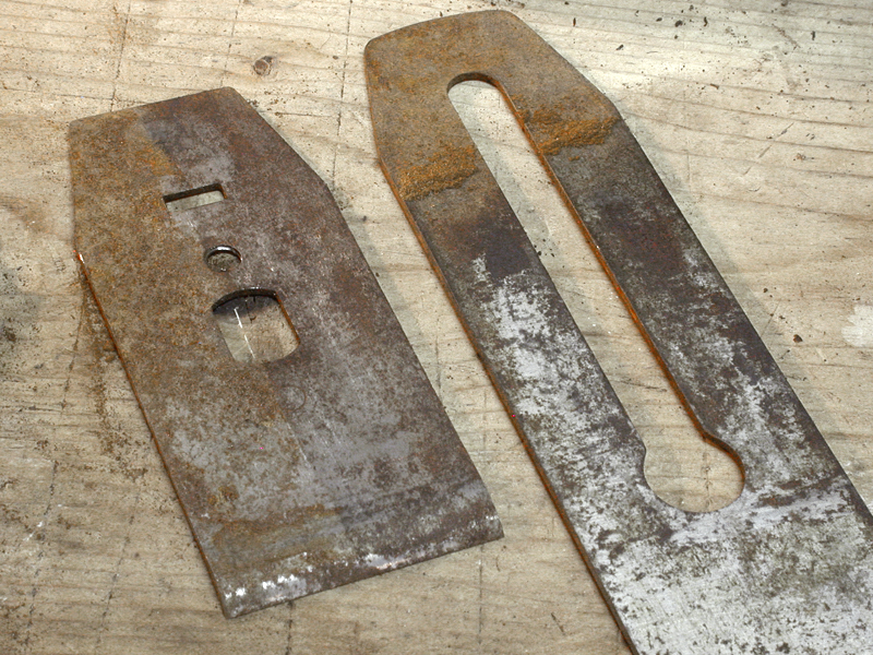
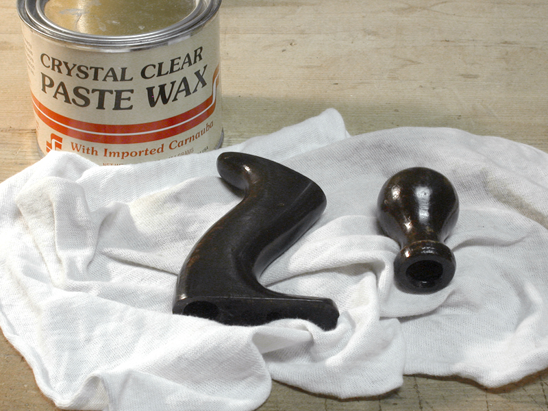
Tools shown in the photos were returned to functional condition by Virginia Toolworks using museum quality archival preservation techniques.  Sharpened and tuned for use, every tool is fully tested and adjusted until perfect.

____________________________________

1. Moxon, Joseph. Mechanick Exercises. London, 1703.

Tool Profile – Millers Falls “Buck Rogers” Planes

Millers Falls Buck Rogers Duo 1

Millers Falls Buck Rogers Planes, nos. 714 and 709 – Virginia Toolworks Collection

Designed by Robert Huxtable, a draftsman at the Millers Falls Company, the no. 709 and no. 714 planes were sold from approximately 1950 to 1960. Based on an earlier Sargent design that was never manufactured, the no. 709 was a smoothing plane comparable in size to a Stanley no. 4, and the no. 714 was a jack plane comparable to the Stanley no. 5.

These tools are commonly referred to as “Buck Rogers” planes by tool collectors, an appropriate nickname given their “futuristic” design qualities, characteristic of 1940s and 50s science fiction and late machine age influences.

Both planes featured striking red knobs and handles made of Tennessee Eastman Tenite #2, a cellulosic plastic originally developed in 1929 that was “guaranteed unbreakable.” They did, however, have a tendency to fade over time, and many seen today appear more orange than the original read.  The frogs had very large seating surfaces and an excellent lateral adjustment design. However, they lacked the precise adjustment ability necessary for fine woodworking, and were therefore considered general carpentry planes.

Two variations (identified as “types” in present day reference) were produced, most readily identified by the change from an unbroken metal slope at the toe in the Type 1 (left in the photo above) to a painted recessed area at the toe in the Type 2 (shown right above). The other major change was the slope angle of the top of the tote, which is flatter in the first type and more pronounced in the later type.

Although these planes were well designed and quite sturdy in their construction, they never really caught on. Perhaps viewed as gimmicky or simply introduced during the unfortunate decline of hand tools in the post war years, the planes were only produced for about 10 years before being discontinued around 1960. While not particularly uncommon on the vintage tool market, well preserved examples are somewhat rare and fetch much higher prices than the common Stanley and other Millers Falls bench planes.

MF_HUXTABLE_BUCK-ROGERS

Original Huxtable Patent Drawing, c. 1950

For more information on the Millers Falls Company and Buck Rogers planes, please visit http://oldtoolheaven.com/bench/buckr.htm.

***

The Confusing Grey Area of Type Study Transitions

Block Planes from the Author's Collection

Block Planes from the Author’s Collection

As I’ve written before, I periodically receive questions from readers.  I really enjoy this, and a few of these questions have led to good friendships along the way.  In a recent correspondence with one of my long distance tool friends, the following question was posed.  I thought it was a good one, and worth sharing…

I have a No 4 type 5 and the iron has the “J” trademark which was allegedly used 1874-1884.  I think it’s original to the plane and the “nut” hole is at the top of the iron. The lateral adj lever is the single piece and everything else adds up. According to the type study (if one goes by that) that particular plane was produced 1885-1888. Now, also according to the type study that plane should likely have an iron with TmP, which I have but the hole is at the bottom of the iron which wasn’t supposed to happen until type 6 planes 1888-1892.  …I know type studies are a modern phenomenon but obviously are used today to determine the approximate time the plane was manufactured and sometimes it has a real effect on the value. …  The type study seems to be a little off on this particular time line but am I putting too much value on the information anyway? I haven’t studied this long enough to understand how the studies determined typing but now I’m not sure that the specificity of subtle changes determining the difference in type is valid. I think my plane has the correct Tm on the iron but a type study would lead someone else to question it.   – Mark

Mark, you nailed it – specificity of subtle changes determining the difference in type is, in fact, NOT always valid.  It’s actually kind of interesting that our brains all seem to want to interpret type studies in a very organized, linear manner.  Strictly speaking, when the type study for Stanley bench planes was created, the transition points from one type to the next were logical from a feature standpoint, but somewhat arbitrary from a date standpoint.  Take your Type 5 to Type 6 transition, for example.  The type study dates the type 5 from 1885 to 1888, and the type 6 from 1888-1892.  While the transition of some features, like the re-design of the frog receiver, probably switched on a specific date, other changes were implemented over time.  And remember that despite what the type study leads us to believe, all the changes implemented (where we mark the transition from one “type” to the next) were not coordinated.

When Roger Smith created the type study, he made judgment calls for when to mark the date of change from one type to the next, which makes sense in the context of a type study.  However, in reality, the transition from one type to the next wasn’t so prescribed, and actually reflects an unspecified period of time in which there would have been a mix of features.  It wasn’t a single month or year in most cases, but likely a period of one to several years.  In a couple of cases, this transition period was so pronounced that the type study includes references to “hybrid” types, as is well documented between types 8 to 9.

The guys at Stanley were brilliant when it came to product differentiation and marketing.  They knew how to keep their line of tools fresh and relevant, and implemented subtle changes to help remain current and sustain demand.  Some of their changes were likely implemented for that reason alone.  The trademark stamp on iron, for example, served no functional purpose.  As such, I imagine that changes from one mark to the next took place independently of most other design changes, and therefore has the least correlation to the type studies.

A lot of people point out that the change from one plane “type” to the next should be interpreted very differently from how we understand the change from one model year car to the next.  This is true.  Comparatively, Stanley’s planes were more like today’s computers, where change is an ongoing evolution rather than a series of annual steps.  Imagine 100 years from now someone trying to create a type study for Microsoft/Intel based personal computers.  I can envision some poor soul trying to understand why his vintage “Type 4” Dell PC has a Pentium IV processor, when the “type study” clearly states it should have a Pentium III.

So, don’t fret, Mark.  What you have is a late type 5 or very early type 6.  The mix of features simply indicates the plane was probably made during that period of transition, and if anything, actually helps narrow the date range.  While you can’t prove it, you’d be quite justified to estimate the date of manufacture to sometime between, say, 1887 and 1889.  And you’d probably be pretty darn close.

 ***