Following the popularity of the recent post, Tune Your Hand Plane Tonight, let’s now talk about block planes. Much of the information will be the same, but block planes are different enough to warrant a dedicated set of instructions. Besides, since there are probably more block planes owned today and sitting unused in garages and workshops than there are bench planes, they deserve a little love of their own.
As I’ve written before, I have a particularly strong affinity for block planes. They are the sexy two seater sports cars of the hand plane world – quick, nimble, and fun to handle. But more than that, they are extraordinarily versatile and practical for many handy-man chores around the house, as well as indispensable tools in the wood shop. Even the most ardent power tool user, and certainly the average homeowner, should have at least one or two block planes in his or her arsenal.
Keeping a block plane in good working order is quite easy. Tuning one for optimal performance is a simple proposition that can be accomplished in an hour or so, if not less. As I did with the bench plane instructions, I’m going to assume that your block plane is already in a mechanically functional condition and doesn’t require a full blown restoration. For that level of detail, I recommend reading the posts under Preservation on the menu bar at the top of the page. Since there are multiple mechanical styles and configurations of block planes, I’m going to try to keep it fairly generic, so you may need to interpolate for your specific plane.
Step 1 – Pour Drink of Preference
 For working on block planes, let’s go with something a little more exotic than the bourbon we enjoy with our bench planes. I recommend Rendezvous Rye from the High West distillery. It is… complex and superb. Of course, what you drink is up to you, but moderation is certainly recommended, for while you won’t be working with electrically powered tools, you will be handling very sharp objects. (5 minutes)
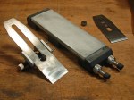
Step 2 – Disassembly & Cleaning
 The second step is to completely disassemble your plane and clean all the parts. Using screwdrivers of the appropriate size, remove all the parts – lever cap, cap bolt, lateral lever, eccentric lever, adjustment screws, knobs, etc. If you’re not completely familiar with what and where everything goes or are worried you might have trouble putting it all back together, take before pictures or notes.
Once disassembled, brush off all the sawdust and dirt. If the filth is excessive, use a toothbrush and orange degreaser (available at the hardware or grocery store). Also take a few minutes to clean the threads and slots on all the screws and bolts. I use a small wire bristle brush with a little turpentine or light penetrating oil like WD-40. Once cleaned, wipe them down and set them out of the way so they don’t attract grit. (10 minutes)
Step 3 – Hello Froggy
 Unlike frogs on bench planes, the frogs on block planes are usually fixed platforms cast into the body of the plane. The top of the frog provides a small platform for the iron to sit, while the flat area behind the mouth offers support near the cutting edge. Both surface areas should be clean of dirt and debris. A toothbrush or brass bristle brush with degreaser works well, although you can also use WD-40 or turpentine. The face of the frog is one of the more critical surfaces of the plane. Once clean, fit the iron against the frog and verify that it sits flat and securely with no wobble. You don’t want any wiggle or movement, so any high spots or irregularities in the casting need to be carefully filed or sanded flat. (5-15 minutes)
Step 4 – Adjustimability of the Mouth
 Many “premium” models of block planes feature an adjustable mouth opening. This typically means the front section of plane’s sole is a separate piece than can be positioned toward the toe (thus opening the size of the mouth) or closer to the iron (closing the size of the mouth opening). It is necessary to periodically remove this piece to clean out sawdust that has accumulated, and to clean and lubricate the tracks upon which the plate rides. If it doesn’t adjust easily forward and back, it needs attention.
Since you’ve already disassembled the plane, make sure both the plate itself and the receiver in which it sits are both clean of debris. Brush the edges of the plate and tracks of the receiver with a brass or wire bristle brush lubricated with light oil or turpentine. Fit the plate in place and verify that it moves fairly freely. It is not normally necessary (nor desirable) to sand the edges of the plate to make it move more easily, although this is sometimes necessary if the plane is vintage and the plate a replacement. If you decide metal removal is absolutely necessary, be careful and go very slow. You can’t un-sand. (5-15 minutes)
Step 5 – Inspect the Sole
 Take a look at the sole (bottom) of the plane. Inspect for dents or dings with raised points around the edges that might dig into your wood surface when planing. If you find any, carefully file them flat with a mill file, followed by a little 220 grit sandpaper. Unlike bench planes, which have a lot more surface area, flattening the sole of a block plane is a relatively painless process. Although not usually a critical requirement, flattening the bottom will often provide superior results in use.
First, temporarily re-install the iron and lever cap and tighten to normal pressure. This ensures the body will be under the same stress (and any possible distortion) as when in actual use. Working against a dead flat substrate such as a granite sharpening block or the iron bed of a table saw, start with 60 grit and go through progressively finer grits until you are satisfied that the toe, heel, and areas just in front of and behind the mouth are all completely flat and smooth. I usually stop with 320 grit. Aluminum Oxide sandpaper is my preference. If you don’t want to invest in a granite sharpening block, granite floor tiles from your local home center are just the right size and cost around $5 each. (30-45 minutes depending)
Step 6 – Time to Sharpen
 Yes, sharpening is the step everyone loves to hate, the step that prevents so many people from ever trying a hand plane. The trick is not to wait until you need to use the tool. Make time for sharpening in advance, and make a party out of it! Okay , so maybe not a party, but there is something truly rewarding about getting an edge you can shave with. It’s relaxing and I really do enjoy it. Since this is not a sharpening tutorial, I’ll leave the particulars on methodology to another post or reference. But if you do nothing else, take the time to put a keen edge on your plane’s iron. A 25 degree bevel works perfectly on most block planes – both low angle and standard angle models. The angle of the plane’s bed varies on these models, usually either 12 degrees for low angle planes or 20 degrees for standard angle planes. Add the 25 degree bevel and you end up with a 37 degree low angle of cut, or a 45 degree standard angle of cut (same as bench planes). Add a micro bevel if you want, and don’t forget to polish the unbeveled back edge. (30 minutes)
Step 7 – Lubrication
 Lubrication is a good idea, but should be done sparingly since oil attracts dirt and grit. I add just a drop of light oil to the threads of all the bolts and screws before re-installing them. I also add a drop to all the moving/adjustment parts, but wipe them with a rag afterward so that only a light film is left. They certainly don’t need to be dripping.
Some guys believe in waxing the sole. Nothing wrong with that as long as you don’t use a silicone based wax. However, I just wipe down all exterior surfaces with a little Jojoba oil for storage. (5 minutes)
Step 8 – Assemble, Adjust, Cut
 Time to put it all back together. Re-attach the eccentric lever and front plate (if it has one), adjustment wheel, lateral lever, knobs, etc. and all related hardware. Carefully put the iron and cap iron assembly in place being careful not to fould the newly sharpened edge, and install the lever cap. It should lock down securely, but not so tight as to inhibit raising and lowering the iron. Adjust the front plate (if it has one) forward or backward as needed for the type of planing you intend to do (again, see open vs closed mouth). Once set, lower the iron into the mouth to take your first test cut. All of your hardware and adjustment mechanisms should move freely and smoothly. (10-15 minutes)
Unless you run into an unexpected problem, the entire tuning and sharpening process can be completed in about 1 to 2-1/2 hours, and even quicker if you’re tuning a new plane or re-tuning a plane that has already been tuned or well cared for. It’s easy, rewarding, and builds both knowledge and confidence in your ability to master hand and block planes.
***


